
Wavelength adjusting device

A wavelength adjustment and temperature sensor technology, applied in the field of spectral testing, can solve the problems of inability to meet laser working efficiency and power stability, low control accuracy, etc.

Active Publication Date: 2013-10-23
上海瀚宇光纤通信技术有限公司
View PDF5 Cites 9 Cited by
  • Summary
  • Abstract
  • Description
  • Claims
  • Application Information

AI Technical Summary

Problems solved by technology

At present, the control of pump temperature is mostly through water cooling or large heat sink for heat dissipation. The control accuracy is not high, and it cannot meet the higher requirements for laser working efficiency and power stability.

Method used


Image

  • Wavelength adjusting device

Examples


Embodiment Construction

[0007] In order to facilitate a further understanding of the wavelength adjustment device of the present invention, the following description will be made in conjunction with the accompanying drawings and embodiments.

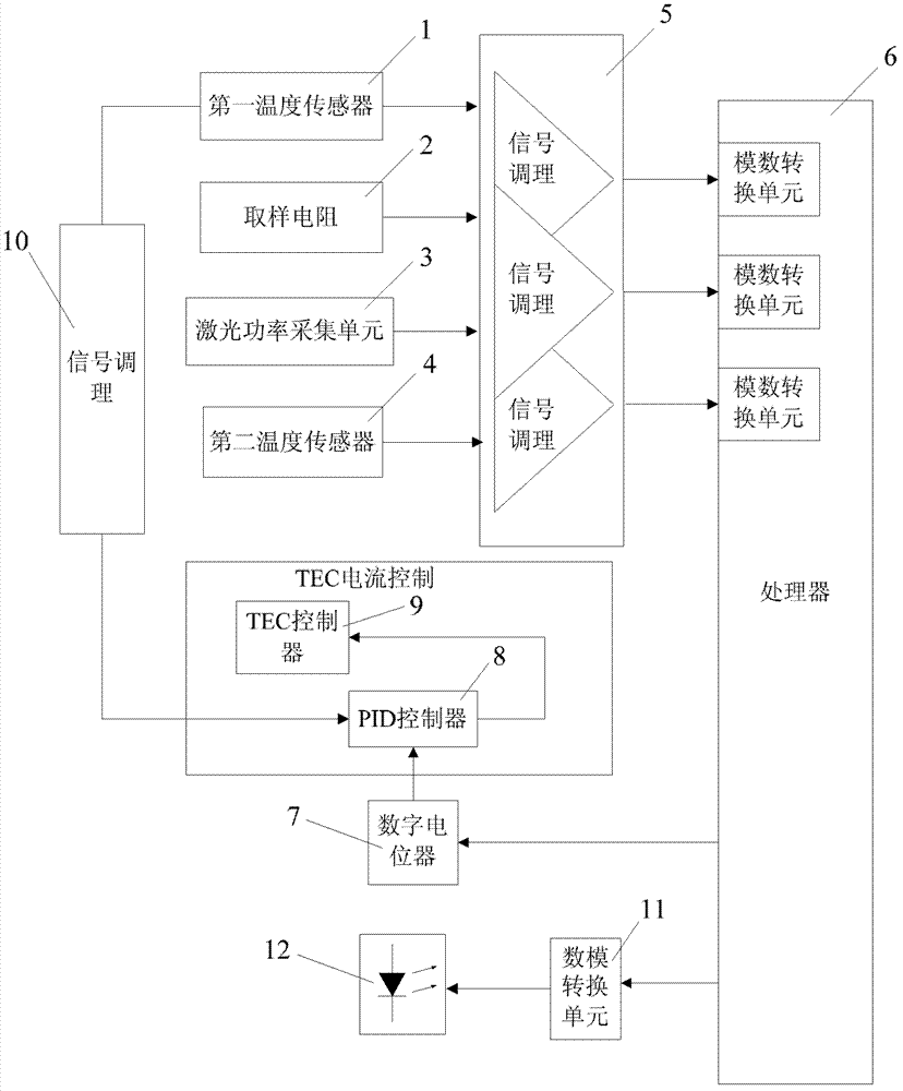
[0008] refer to figure 1 As shown, the wavelength adjustment device of the present invention includes: a first temperature sensor 1, used to collect the temperature of the pump surface; a sampling resistor 2, connected to the input end of the pump power supply, used to collect the pump working current; a laser The power collection unit 3 is arranged at the laser transmitting end to collect the laser power. The laser power collection unit 3 first decomposes the emitted laser light into an output laser and a detection laser through a beam splitter, and then cooperates with a photoelectric conversion unit to receive the laser power. The above detection laser is converted into an electrical signal output; a second temperature sensor 4 is used to collect the externa...


PUM


Abstract

A wavelength adjusting apparatus is disclosed, comprising a first temperature sensor, a sampling resistor, a laser power acquisition unit and a second temperature sensor, wherein the first temperature sensor, the sampling resistor, the laser power acquisition unit and the second temperature sensor are connected with the input end of a processor through a signal conditioning unit; the output end of the processor is connected with the input end of a digital potentiometer; the input end of the digital potentiometer is connected with the input end of a PID controller; the output end of the PID controller is connected with the input end of a TEC controller; the first temperature sensor is directly connected with the input end of the PID controller through another signal conditioning unit. Through accurate control over pump temperature, pump operating wavelength is largely kept unchanged in optical fiber laser output power changing processes, active optical fibers are enabled to work in the condition characterized by optimum absorption wavelength, and the working efficiency and the power stability of a laser are improved.

Description

technical field [0001] The invention relates to the field of spectrum testing, in particular to a wavelength controller of a high-power fiber laser. Background technique [0002] For high-power fiber lasers, it is necessary to adjust the output power of the laser by adjusting the pump power. The change of the pump power will lead to the change of the pump temperature, and the pump wavelength changes with the change of the pump temperature. The change of the pump wavelength will affect the absorption efficiency of the active fiber, resulting in the instability of the output power of the laser. Therefore, keeping the pump operating temperature constant to achieve the purpose of stabilizing the pump wavelength is the main means to ensure the stability of the laser output power. At present, the pump temperature is mostly controlled by water cooling or a large heat sink for heat dissipation. The control accuracy is not high, and it cannot meet the higher requirements for laser ...

Claims


Application Information

Patent Timeline
Patent Type & Authority Applications(China)
IPC IPC(8): H01S3/13H01S3/131
Inventor 张一平
Owner 上海瀚宇光纤通信技术有限公司
Learn More