Electric heating pipe for heating liquid

An electric heating tube and liquid technology, which is applied in the field of electric heating tubes, can solve the problems of large temperature difference, leakage of electricity, danger of electric shock to people in the liquid, etc., and achieves the effects of not easy to burst, preventing device bursting, and convenient installation.

Active Publication Date: 2013-10-23
LITTLE STONE CERAMIC BLADE ZHONGSHAN CO LTD
View PDF6 Cites 8 Cited by
  • Summary
  • Abstract
  • Description
  • Claims
  • Application Information

AI Technical Summary

Problems solved by technology

Due to the material characteristics of ceramic tubes and quartz tubes, when the cold liquid flows through the tube and contacts the hot tube wall, the temperature difference is large, and sudden cooling and sudden heating will cause the ceramic tube or quartz tube to burst. Once the ceramic tube or quartz tube When the tube bursts, the liquid will directly contact the heating film, and the heating film is energized, resulting in electric leakage, and people who use the liquid are in danger of electric shock

Method used


Image

  • Electric heating pipe for heating liquid
  • Electric heating pipe for heating liquid
  • Electric heating pipe for heating liquid

Examples


Embodiment 1

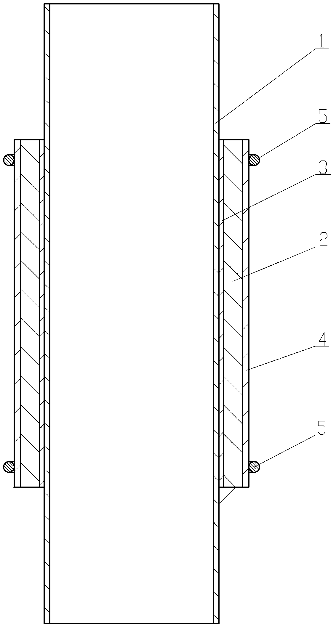
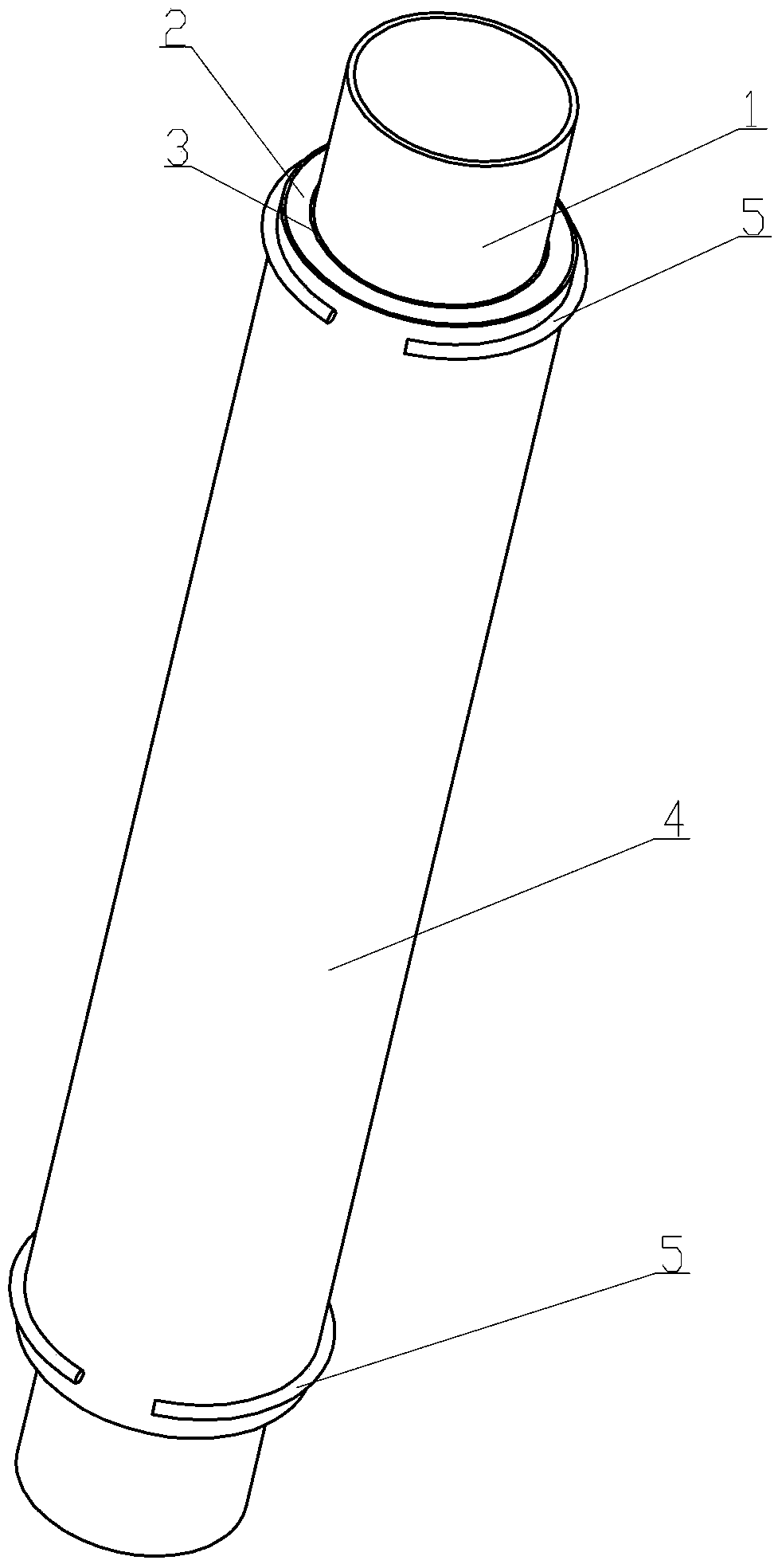
[0021] Example 1, such as Figure 1 to Figure 2 As shown, an electric heating tube for heating a liquid includes a metal tube 1, and the liquid to be heated flows through the metal tube 1. The metal tube 1 can be a stainless steel tube, an aluminum tube or a copper tube, or other metal tubes , the thickness of the tube wall is less than or equal to 2mm, which can ensure its heat transfer efficiency. The metal tube 1 is provided with an insulating layer 2, and the insulating layer 2 mainly plays an insulating role. It can be a ceramic tube, a quartz glass tube or a microcrystalline stone tube and the like, and the insulating layer 2 can be an insulator. It is a hollow cylindrical body set outside the metal pipe 1, so that the insulating layer 2 passing through the hollow cylindrical body is set on the metal pipe. There is a heat conduction layer 3 between the metal pipe 1 and the ceramic pipe 2. The heat conduction layer 3 is a heat conduction oil layer. The heat conduction oi...

Embodiment 2

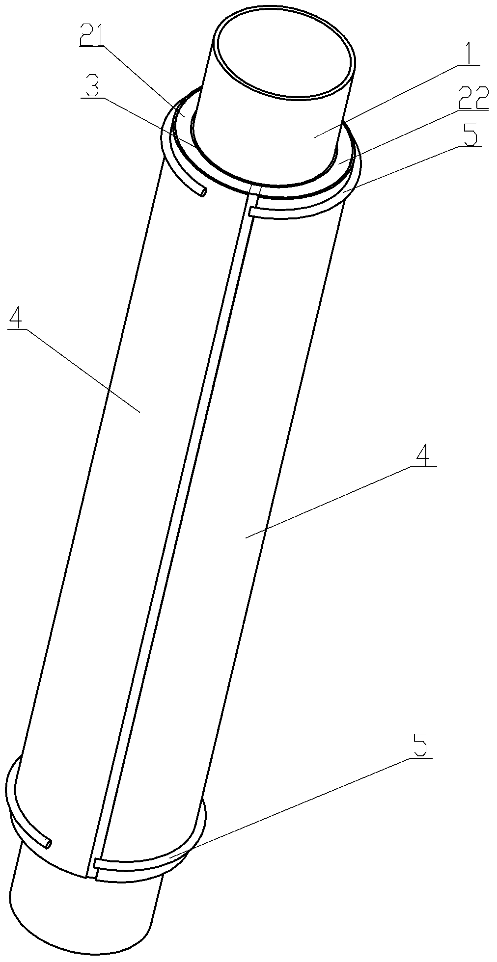
[0022] Example 2, such as Figures 3 to 4 As shown, the difference from Embodiment 1 is that the insulating layer 2 is different. Specifically, the insulating layer 2 is a sheet-like body that surrounds the outer wall of the metal tube 1, and can be one or more sheet-like bodies that surround the outer wall of the metal tube 1. , can use 2 pieces, 3 pieces, 4 pieces, 6 pieces, etc., the best implementation mode is to use two pieces, the metal pipe 1 can be a hollow circular pipe, and the two insulation layers 2 can be attached to the outer wall of the metal pipe 1 The left arc-shaped piece 21 and the right arc-shaped piece 22 , the left arc-shaped piece 21 and the right arc-shaped piece 22 basically wrap the outer wall of the metal pipe 1 . The insulating layer 2 is composed of two semi-arc-shaped sheets, mainly for the purpose of effectively contacting the outer wall of the metal pipe 1 in different thermal expansion and contraction ranges to improve thermal efficiency, and t...


PUM


Abstract

The invention relates to an electric heating pipe for heating liquid. The technical points are as follows: the electric heating pipe comprises a metal pipe, an insulation layer is arranged outside the metal pipe, a heat conducting layer is arranged between the metal pipe and the insulation layer, a heating membrane is arranged outside the insulation layer, and electrodes for leading current to the heating membrane are arranged on the heating membrane. The electric heating pipe has a simple structure and high heat transfer performance and safety performance, and the whole device can be effectively prevented from explosion.

Description

【Technical field】 [0001] The invention relates to an electric heating tube, in particular to an electric heating tube for heating liquid. 【Background technique】 [0002] Electric heating tubes are mainly used in kettles, water heaters, water dispensers, etc. Existing thin-film heating electric heating tubes generally include ceramic tubes or quartz tubes, and a heating film is coated on the outside of the ceramic tube or quartz tube. The heating film supplies power to it through electrodes. The tube or quartz tube is transferred to the liquid in the tube, thereby heating the liquid (such as water, etc.) in the ceramic tube or quartz tube, so that the liquid can be heated quickly. Due to the material characteristics of ceramic tubes and quartz tubes, when the cold liquid flows through the tube and contacts the hot tube wall, the temperature difference is large, and sudden cooling and sudden heating will cause the ceramic tube or quartz tube to burst. Once the ceramic tube or...

Claims


Application Information

Patent Timeline
Patent Type & Authority Applications(China)
IPC IPC(8): H05B3/42H05B3/10
Inventor 吴让攀
Owner LITTLE STONE CERAMIC BLADE ZHONGSHAN CO LTD
Why Eureka
Try Eureka