Textile drying machine

A dryer and textile technology, applied in dryers, drying, progressive dryers and other directions, can solve the problems of low reliability, low work efficiency, shortened service life, etc., to improve the reliability of use, work High efficiency and guaranteed service life

Inactive Publication Date: 2017-12-29
JIANGSU GUANGSHENGYUAN TECH DEV
View PDF0 Cites 6 Cited by
  • Summary
  • Abstract
  • Description
  • Claims
  • Application Information

AI Technical Summary

Problems solved by technology

[0002] As we all know, textiles will contain a certain amount of water vapor after ironing, which will affect the quality of textiles. The textile dryer is a method of drying textiles after ironing to remove the water vapor attached to textiles to ensure The quality of textiles, and the device for preventing mildew and deterioration during the transportation of textiles; the existing textile dryer includes a box body, a placement plate and a fan. The opening communicates with the working chamber, and a door panel is arranged at the opening, the front end of the right side wall of the door panel is hinged to the front end of the opening, the rear end of the right side wall of the door panel is detachably fixed to the rear end of the opening, and a handle is provided on the door panel, The placing board is located in the working chamber, the left end of the placing board is connected with the left side wall of the working chamber, the right end of the placing board is connected with the right side wall of the working chamber, and the top of the fan is connected with the top wall of the working chamber; when working, the handle is manually pulled to drive the door panel Open it, place the textiles on the placement board, close the door, turn on the fan, the output end of the fan outputs wind, and dry the textiles on the placement board, then turn off the fan, open the door, and take out the dried textiles However, it is found in the use of this textile dryer that the number of drying times is small and the work efficiency is low; and the interior is closed during work, and the gas cannot be discharged from the working chamber, which is prone to bursting and reduces its service life. resulting in lower reliability

Method used


Image

  • Textile drying machine
  • Textile drying machine

Examples


Embodiment Construction

[0013] The specific implementation manners of the present invention will be further described in detail below in conjunction with the accompanying drawings and embodiments. The following examples are used to illustrate the present invention, but are not intended to limit the scope of the present invention.

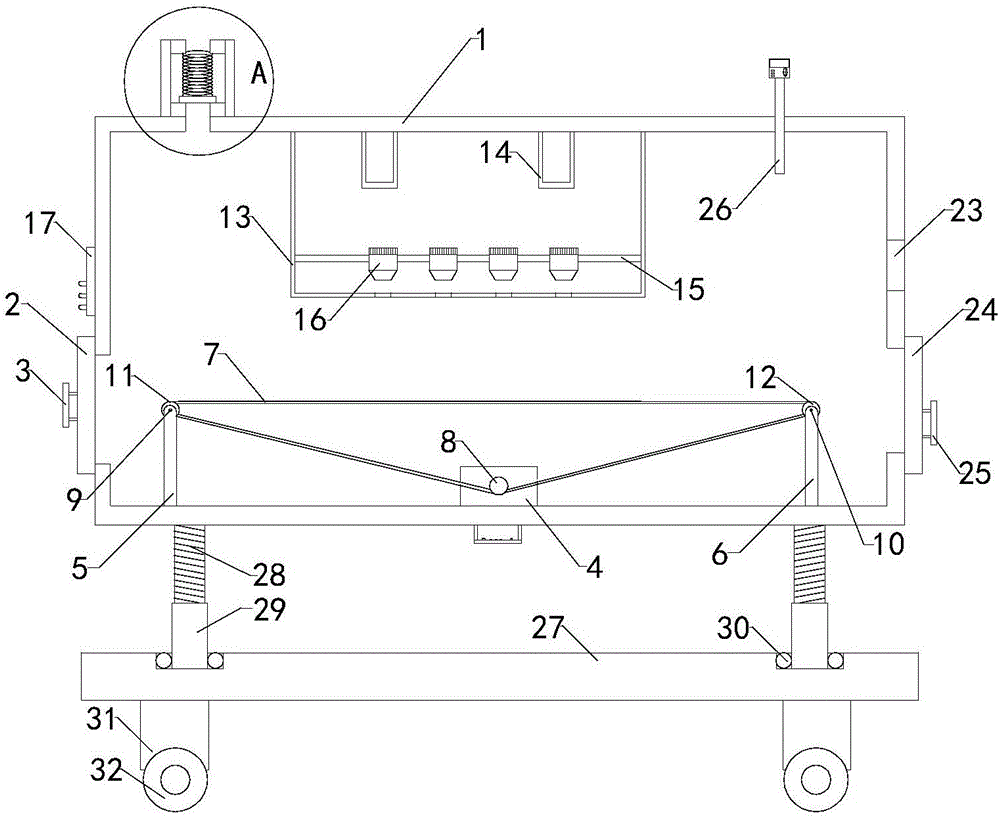
[0014] The textile dryer of the present invention comprises a box body 1, a placement plate and a fan, a working cavity is arranged in the box body, an opening is arranged on the left side wall of the box body, the opening communicates with the working cavity, and a door panel 2 is arranged at the opening The front end of the right side wall of the door panel is hinged to the front end of the opening, the rear end of the right side wall of the door panel is detachably fixed to the rear end of the opening, and a handle 3 is arranged on the door panel; it also includes a servo motor 4, a set of left support frames 5, One set of right support frame 6 and conveyor belt 7, the ...


PUM


Abstract

The invention relates to the technical field of textile processing and in particular relates to a textile drying machine. The textile drying machine dries a textile repeatedly, so that the work efficiency is relatively high; the textile drying machine is not closed inside during work, so that residual gas in a working cavity can be immediately removed and is unlikely to burst, and therefore, the service life of the textile drying machine is guaranteed, and the using reliability of the textile drying machine is improved; the textile drying machine comprises a box body, a placing plate and a fan. The working cavity is formed in the box body, an opening is formed in the left side wall of the box body, a door plate is arranged on the opening, and a handle is arranged on the door plate; the textile drying machine also comprises a servo motor, a left supporting rack, a right supporting rack and a conveyor belt; the textile drying machine also comprises a heating box, two silicon carbide rods, a fan supporting rack, a plurality of fans and a temperature controller. A heating cavity is formed in the heating box. The textile drying machine also comprise a one-way exhaust valve, an exhaust cavity is formed in the one-way exhaust valve, and a lower exhaust baffle plate, an upper exhaust baffle plate, an exhaust spring and an exhaust baffle plate are arranged in the exhaust cavity.

Description

technical field [0001] The invention relates to the technical field of textile processing, in particular to a textile dryer. Background technique [0002] As we all know, textiles will contain a certain amount of water vapor after ironing, which will affect the quality of textiles. The textile dryer is a method of drying textiles after ironing to remove the water vapor attached to textiles to ensure The quality of textiles, and the device for preventing mildew and deterioration during the transportation of textiles; the existing textile dryer includes a box body, a placement plate and a fan. The opening communicates with the working chamber, and a door panel is arranged at the opening, the front end of the right side wall of the door panel is hinged to the front end of the opening, the rear end of the right side wall of the door panel is detachably fixed to the rear end of the opening, and a handle is provided on the door panel, The placing board is located in the working c...

Claims


Application Information

Patent Timeline
Patent Type & Authority Applications(China)
IPC IPC(8): F26B15/18F26B21/00F26B21/10F26B25/00F26B25/06
CPCF26B15/18F26B21/001F26B21/004F26B21/10F26B25/00F26B25/009F26B25/06
Inventor 金传广尤汉春宋大顺李欣欣陈西府徐晓洪刘兆诚
Owner JIANGSU GUANGSHENGYUAN TECH DEV
Why Eureka
Try Eureka