
Motor rotation shaft assembly method and assembly machine implementing same

A technology of a motor shaft and an assembly method, which is applied to electromechanical devices, manufacturing motor generators, and assembling machines, etc., can solve the problems of high cost, difficulty in recruiting workers, and inability to cope with large-scale production.

Pending Publication Date: 2018-11-06
广东英达思迅智能制造有限公司
View PDF0 Cites 18 Cited by
  • Summary
  • Abstract
  • Description
  • Claims
  • Application Information

AI Technical Summary

Problems solved by technology

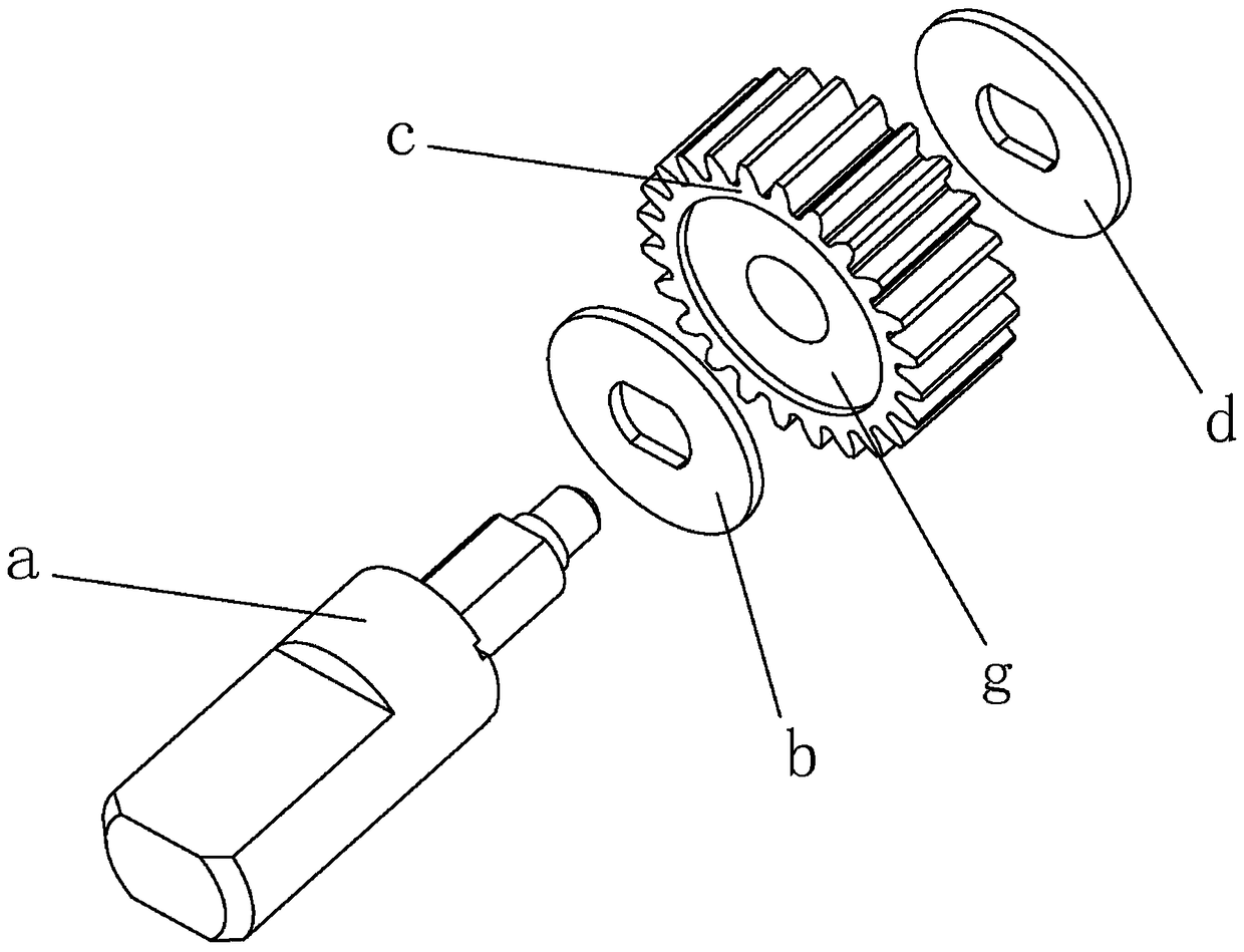
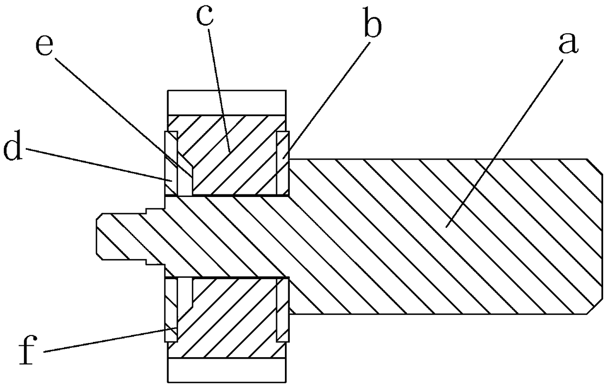
[0002] At present, DC motors are widely used in the world, and are used in many fields such as machinery, toys, and household appliances. There is an existing motor shaft such as figure 1 and figure 2 As shown, it consists of a shaft a, a lower pressure ring b, a gear c, and an upper pressure ring d that are sleeved on the upper end of the shaft a from top to bottom. The upper pressure ring mounting groove f of the pressure ring d, and the lower pressure ring installation groove g for accommodating the lower pressure ring b are provided on the reverse side of the gear c, and lubricating oil needs to be injected between each part, which is manually assembled by workers during assembly Complete, requires separate riveting equipment for riveting, also requires separate friction testing equipment for testing, the assembly speed is slow and the efficiency is low; in addition, due to the high labor cost in China at this stage, it is becoming more and more difficult for enterprises to recruit workers, so this kind of The cost of assembly and assembly is high and cannot cope with mass production

Method used


Image

  • Motor rotation shaft assembly method and assembly machine implementing same
  • Motor rotation shaft assembly method and assembly machine implementing same
  • Motor rotation shaft assembly method and assembly machine implementing same

Examples


Embodiment Construction

[0077] refer to Figure 1 to Figure 18 , an assembly method of a motor shaft, comprising the following steps:

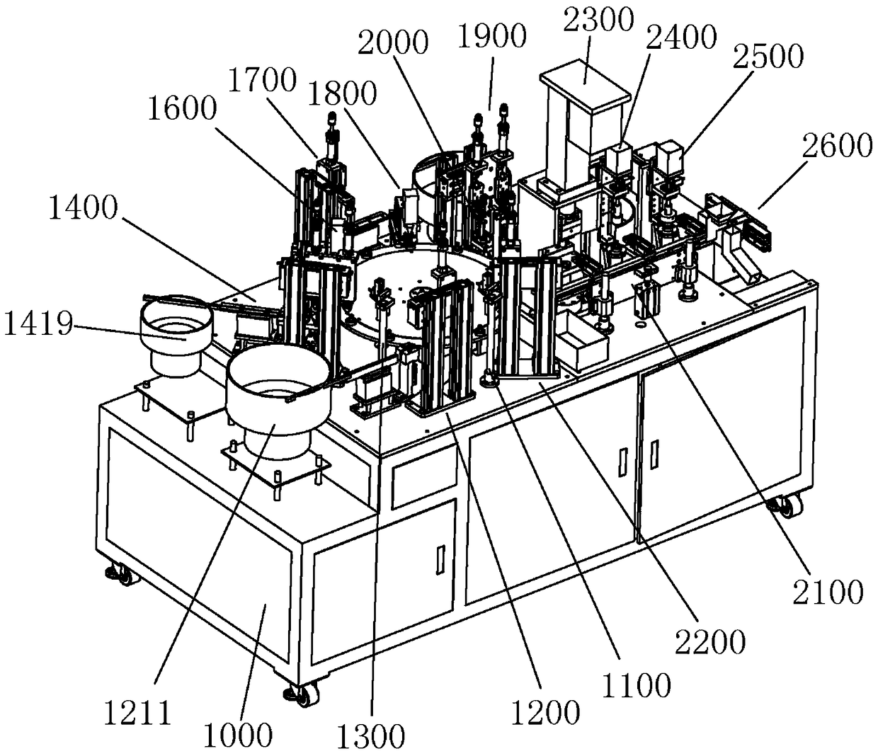
[0078] (1) A circular turntable is set on a machine table, and the turntable is connected with a first motor which drives it to rotate in the circumferential direction but not to move axially. The upper edge of the turntable is fixedly installed with several circularly arranged The shaft fixing seat for accommodating the lower end of the shaft is provided with a shaft fixing seat detection device around the turntable, a shaft delivery installation device, a shaft detection device, a lower pressure ring delivery installation device, a lower pressure ring detection device, and a second pressure ring detection device. An oiling device, a gear conveying and installing device, a second oiling device, an upper pressing ring conveying and installing device, an upper pressing ring detecting device, a finished product moving device and a defective product recovery device, the...


PUM


Abstract

The invention discloses a motor rotation shaft assembly method comprising the steps as follows: a rotary disc is arranged on a machine stand, and an axis rod fixed seat detection device, an axis rod transportation and installation device, an axis rod detection device, a lower pressing ring transportation and installation device, a lower pressing ring detection device, a first oil injection device,a gear transportation and installation device, a second oil injection device, an upper pressing ring transportation and installation device, an upper pressing ring detection device, a finished product moving device and a defective product recycling device are arranged around the rotary disc; a riveting device, a running-in device, a friction force detection device and a sorting device are installed on one side of the rotary disc; and a PLC control system for controlling the device is also installed on the machine stand. Five processes such as automatic assembling, riveting, detecting slippingfriction force and sorting are combined together. The invention also discloses equipment for implementing the method. According to the equipment and the method, the product friction force is controlled in a closed loop, the degree of automation is high, the production cycle of products is effectively shortened, the production cost is reduced; during a production process, detection can be performed according to user demands and product characteristics, the production status can be conveniently better analyzed, an alarm can be given for the abnormal condition during the production process; theproduction abnormity can be eliminated in time, and the product qualification ratio is ensured.

Description

technical field [0001] The invention relates to a machine and a method for assembling a motor shaft using the machine, in particular to an assembling method for a motor shaft and an assembly machine implementing the method. Background technique [0002] At present, DC motors are widely used in the world, and are used in many fields such as machinery, toys, and household appliances. There is an existing motor shaft such as figure 1 and figure 2 As shown, it consists of a shaft a, a lower pressure ring b, a gear c, and an upper pressure ring d that are sleeved on the upper end of the shaft a from top to bottom. The upper pressure ring mounting groove f of the pressure ring d, and the lower pressure ring installation groove g for accommodating the lower pressure ring b are provided on the reverse side of the gear c, and lubricating oil needs to be injected between each part, which is manually assembled by workers during assembly Complete, requires separate riveting equipment...

Claims


Application Information

Patent Timeline
Patent Type & Authority Applications(China)
IPC IPC(8): H02K15/14B23P21/00
CPCH02K15/14B23P21/006
Inventor 吴辉君李振海吴明旭李雄辉徐兴李剑锋
Owner 广东英达思迅智能制造有限公司
Learn More