Supercharge Your Innovation With Domain-Expert AI Agents!

Motor controller

A control device and motor technology, applied in motor generator control, AC motor control, electronic commutation motor control, etc., can solve problems such as Δθr angle error, achieve the effect of low processing load and improve stability

Active Publication Date: 2013-10-23
三电株式会社
View PDF5 Cites 4 Cited by
  • Summary
  • Abstract
  • Description
  • Claims
  • Application Information

AI Technical Summary

Problems solved by technology

[0010] However, the virtual axis is only the assumed axis in the contro

Method used


Image

  • Motor controller
  • Motor controller
  • Motor controller

Examples


Embodiment Construction

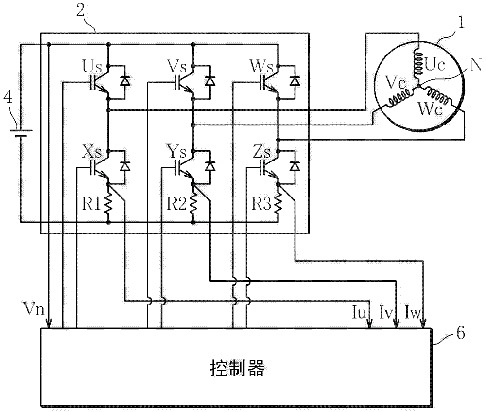
[0053] figure 1 It is a configuration diagram of the motor control device according to Embodiment 1 of the present invention. The motor control device is composed of a motor 1 , an inverter 2 , a DC power supply 4 , and a controller 6 incorporating a microcomputer.

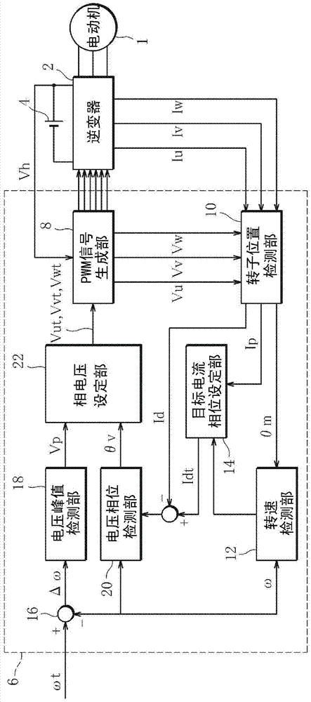
[0054] figure 2 It is a control block diagram showing sensorless control of the motor 1 by the controller 6 . The controller 6 includes: a PWM signal generation unit 8, a rotor position detection unit (rotor position detection unit) 10, a rotational speed detection unit (rotational speed detection unit) 12, a target current phase setting unit 14, an adder 16, and a voltage peak detection unit 18 , a voltage phase detection unit 20 , and a phase voltage setting unit (phase voltage setting unit) 22 .

[0055] The motor 1 is a three-phase brushless DC motor and has an unillustrated stator including three-phase coils (U-phase coil Uc, V-phase coil Vc, and W-phase coil Wc) and an unillustrated rotor including pe...


PUM


Abstract

The invention aims to provide a motor controller. A phase voltage setting means defines an actual current phase range that includes a current phase error range obtained on the basis of parameters containing instrumental errors of the motor and/or an inverter; defines a stable operating current phase range in which a rotor position can be detected through sensorless control; and sets a target current that is obtained by adding a predetermined phase difference, which corresponds to a revolution speed detected by a revolution speed detection means, to a current that is set by means of current vector control, such that the actual current phase range falls within a stable operating current phase range.

Description

technical field [0001] The present invention relates to a motor control device, and more specifically, to a motor control device for variable-speed control of a permanent magnet synchronous motor by sensorless control. Background technique [0002] Permanent magnet synchronous motors (Permanent Magnetic Synchronous Motor: PMSM), especially interior permanent magnet synchronous motors (Interior Permanent Magnetic Synchronous Motors) with permanent magnets embedded in the rotor, are high-efficiency motors with a large variable speed range. :IPMSM) has been widely used in applications such as motors for driving compressors in vehicle air conditioners and motors for driving electric vehicles, and its demand is expected. [0003] A motor control device that controls the driving of such a motor is composed of a motor, an inverter, a DC power supply, and a controller incorporating a microcomputer. [0004] During the operation of the above-mentioned motor, the controller usu...

Claims


Application Information

Patent Timeline
IPC IPC(8): H02P21/00H02P6/06H02P27/04H02P6/18H02P6/08H02P6/15H02P6/17H02P6/182H02P6/28H02P21/13H02P21/18H02P21/22H02P21/24H02P21/28H02P23/16H02P27/08
CPCH02P6/001H02P6/18H02P21/0035H02P27/08H02P21/0042H02P21/26
Inventor 塚本健郎广野大辅
Owner 三电株式会社
Features
  • R&D
  • Intellectual Property
  • Life Sciences
  • Materials
  • Tech Scout
  • Unparalleled Data Quality
  • Higher Quality Content
  • 60% Fewer Hallucinations
Learn More