Patient interface equipment and method for aligning adjacent cervical vertebras by aid of same

A patient interface, patient technology, applied in fractures, non-surgical orthopedic operations, passive exercise equipment, etc., can solve problems such as discomfort, numbness, and deterioration

Inactive Publication Date: 2013-10-30
BEIJING RYZUR AXIOM MEDICAL INVESTMENT
View PDF7 Cites 2 Cited by
  • Summary
  • Abstract
  • Description
  • Claims
  • Application Information

AI Technical Summary

Problems solved by technology

This is due to the presence of blood vessels and neural structures that can be degraded by a particular impact, causing discomfort, numbness, or lowering of the spine by conscious and subconscious contraction of paraspinal muscles that resist therapeutic spinal decompression Effectiveness of Stress Reduction Therapy

Method used


Image

  • Patient interface equipment and method for aligning adjacent cervical vertebras by aid of same
  • Patient interface equipment and method for aligning adjacent cervical vertebras by aid of same
  • Patient interface equipment and method for aligning adjacent cervical vertebras by aid of same

Examples


Embodiment Construction

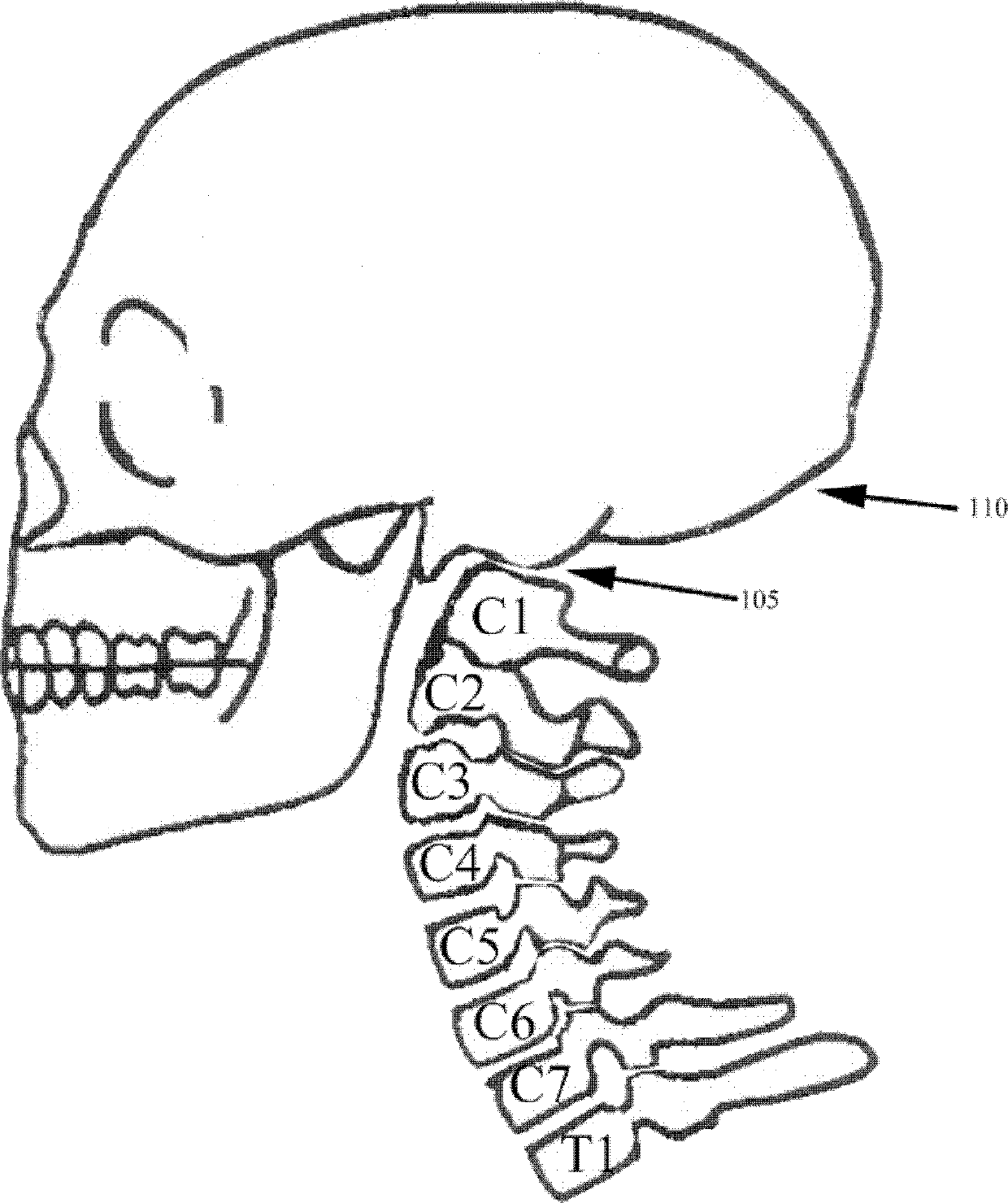
[0059] figure 1 A side view of the patient's skull 110 and cervical spine up to T1 is shown, with the cervical spine in a lordotic state and the skull 110 at a neutral angle, neither flexion nor extension. The base of the skull 110 and the occipital portion CO and the atlanto-occipital joint 105 are shown. The cervical vertebrae are labeled C1, C2, C3, C4, C5, C6 and C7. The first thoracic vertebra is labeled T1. In this regard, although the cervical spine and skull 110 are shown vertically, as if the patient were standing, the figure illustrates the plane that the back of the skull would be in if parallel to the patient's back.

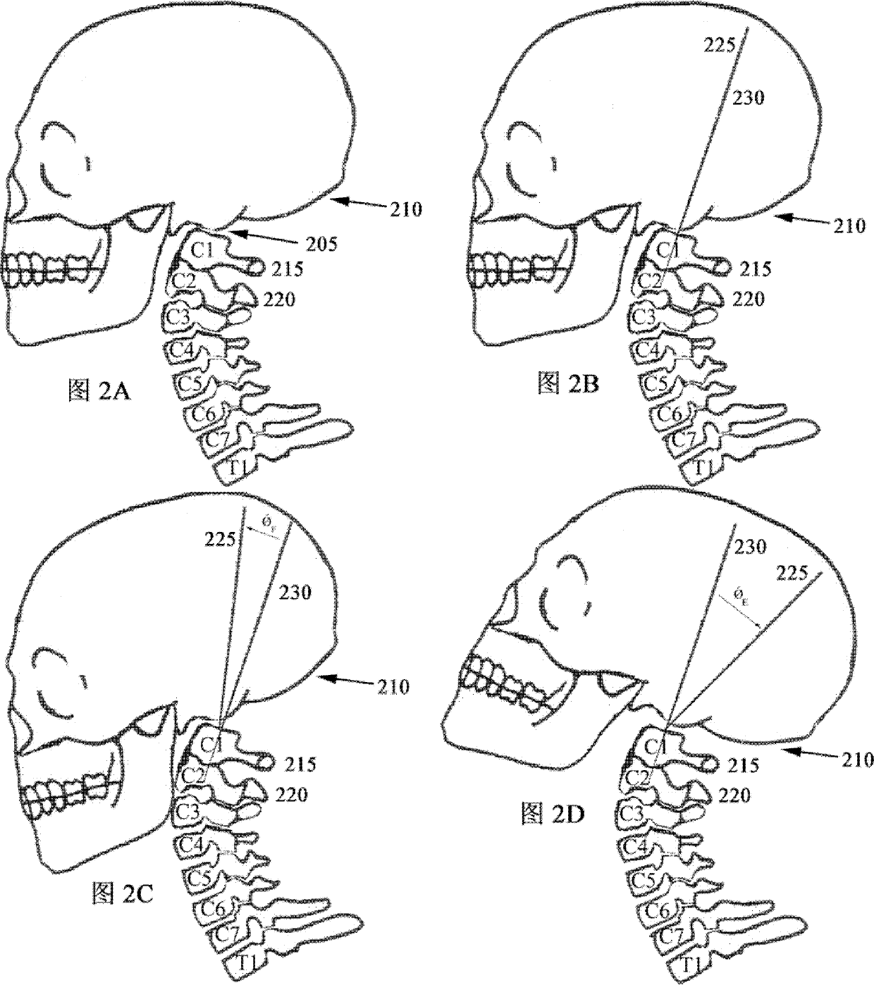
[0060] in the upper left corner of Figure 2A show figure 1 The skull 210 and cervical spine, atlanto-occipital joint 205 are at a neutral angle, neither flexing nor extending. in the upper right corner Figure 2B view with Figure 2A in the same. HPT line 230 is drawn parallel and collinear with C1-C2 215-220. HPT line 225 is drawn from atl...


PUM


Abstract

The invention relates to patient interface equipment and a method for aligning adjacent cervical vertebras by the aid of the same. The patient interface equipment comprises patient positioning devices. The patient positioning devices are configured in such a manner that a target area of the cervical spine of a patient can be repeatedly aligned, the skull of the patient can be positioned and maintained relative to the cervical spine of the patient so as to extent the atlanto-occipital joint of the patient, side-to-side movement of the skull and the cervical spine of the patient is reduced or eliminated, and a curve of the cervical spine of the patient is supported. The patient interface equipment is operationally configured in such a manner that exerted tension is shifted to the patient positioning devices and acts on the occipital bone of the patient, and the patient positioning devices are allowed to move angularly and are allowed to move towards or far away from the shoulders of the patient. The patient interface equipment and the method have the advantage that the skull of the patient can be properly aligned relative to the cervical vertebras of the patients, so that centralized decompression for the cervical intervertebral disc of the patient can be affected to a certain extent.

Description

technical field [0001] The present invention relates to a patient interface device and method of aligning adjacent cervical vertebrae using the patient interface device. More specifically, the method of the present invention applies tension to a patient's cervical spine through a range of angles, and the method dynamically accounts for and adjusts the treatment angle based on patient position. More specifically, the present invention addresses the proper alignment of a patient's skull relative to the cervical vertebrae to, in part, effect the focused decompression of the cervical discs. Background technique [0002] Physiotherapists use spinal decompression therapy to treat a variety of spinal conditions, including herniated discs, degenerative disc disease, sciatica, posterior facet syndrome, and post-surgical pain. Decompression therapy derives from traditional traction-based therapy in which the spine is placed in tension by an external force (eg, by the hands of a physi...

Claims


Application Information

Patent Timeline
Patent Type & Authority Applications(China)
IPC IPC(8): A61F5/045
CPCA61H2201/1676A61H1/0296A61H2201/5061A61F5/01A61H2201/1607A61H2201/5005A61H2203/0456A61H1/02A61F5/05883
Inventor 任嵩
Owner BEIJING RYZUR AXIOM MEDICAL INVESTMENT
Why Eureka
Try Eureka