

Whole aeration cyclone vertical shaft
A shaft, the whole process technology, applied in the field of aeration and corrosion reduction, to achieve the effect of high operation safety, ingenious conception and easy construction
- Summary
- Abstract
- Description
- Claims
- Application Information
AI Technical Summary
Problems solved by technology
Method used
Image

Examples
Embodiment 1
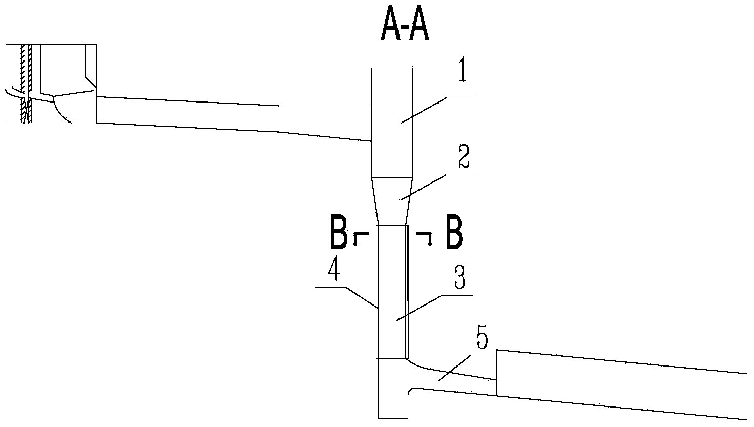
[0028] The swirl shaft of the whole process aeration provided in this embodiment is as follows: image 3 As shown, the swirl shaft is set on the vertical wall surface of the entire vertical shaft section 3 below the contraction section 2 of the conventional vertical shaft spillway and above the exit of the lower flat section 5 along the radial direction, and is provided with 2 channels running through the whole process. Air sill 4, the aeration sill 4 gradually closes to the wall surface formed by the original radius of shaft 3 with a smooth curved surface after sudden expansion, see Figure 4 . The aeration sill 4 provided can ensure that when the water flow rotates against the wall, an aeration cavity 6 will be generated, so that the water flowing through the wall of the entire shaft 3 is aerated water flow with a high concentration of gas, so as to completely avoid the aeration of the shaft. Cavitation erosion damage occurs on the wall surface.
[0029] From Figure 5 It...
Embodiment 2
[0031] The swirl shaft of the whole process aeration provided in this embodiment is as follows: Figure 6 As shown, the difference from the fully aerated cyclone shaft given in Example 1 is that the two aeration sills 4 provided in the shaft section 3 extend all the way to the bottom plate of the shaft, which is conducive to simple construction. All the other reasons are identical with embodiment 1, slightly.
Embodiment 3
[0033] The swirl shaft of the whole process aeration provided in the present embodiment is as follows: Figure 7 , 8 As shown, the difference from the full-process aerated swirl shaft given in Example 1 is that: 1) the two aeration sills 4 set in the shaft section 3 extend all the way to the bottom plate of the shaft; 2) the shaft section 3 is provided with There are 4 aeration sills, and the 4 aeration sills are evenly distributed in the circumferential direction of the shaft section. All the other reasons are identical with embodiment 1, slightly.
PUM
 Abstract
Description
Claims
Application Information