High temperature melt discharge pipe and smelting furnace with same

A discharge pipe and melt technology, applied to furnaces, crucible furnaces, furnace components, etc., can solve problems such as unsafety, shortened service life, furnace wall oxidation, etc., and achieve the effect of reducing safety hazards

Inactive Publication Date: 2013-10-30
四川绿冶科技有限责任公司
View PDF6 Cites 9 Cited by
  • Summary
  • Abstract
  • Description
  • Claims
  • Application Information

AI Technical Summary

Problems solved by technology

However, in the existing metallurgical smelting of intermediate frequency furnaces, the smelting liquid is discharged by dumping, which is not only unsafe when pouring, but also has a large heat loss, and the smelting liquid is easily oxidized, and the furnace wall is also prone to oxidation, which shortens the service life.
In the field of casting, it cannot meet the needs of the continuous casting process for melting liquid

Method used


Image

  • High temperature melt discharge pipe and smelting furnace with same
  • High temperature melt discharge pipe and smelting furnace with same

Examples


Embodiment 1

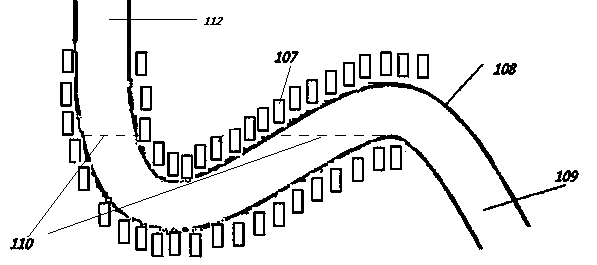
[0018] Embodiment 1: A discharge pipe for high-temperature melt, including a pipe with a submerged water bend structure, and an intermediate frequency power supply coil for heating wound outside the pipe wall; the pipe wall is made of high-temperature-resistant materials; Intermediate frequency power supply coil 107; one end of the tubular structure communicates with the furnace chamber through the bottom and / or lower part of the smelting furnace body; at the beginning of smelting, the melt flows into the liquid surface line 110 of the submerged water bend, deposits, cools and solidifies, and then blocks the pipeline. When the melt in the furnace cavity needs to be discharged from the furnace cavity, power is transmitted to the intermediate frequency power supply coil 107 wound on the pipeline, so that the smelting material in the submerged water bend is melted rapidly, and the melt in the furnace cavity is discharged from the pipeline, and then the valve is closed. The interme...

Embodiment 2

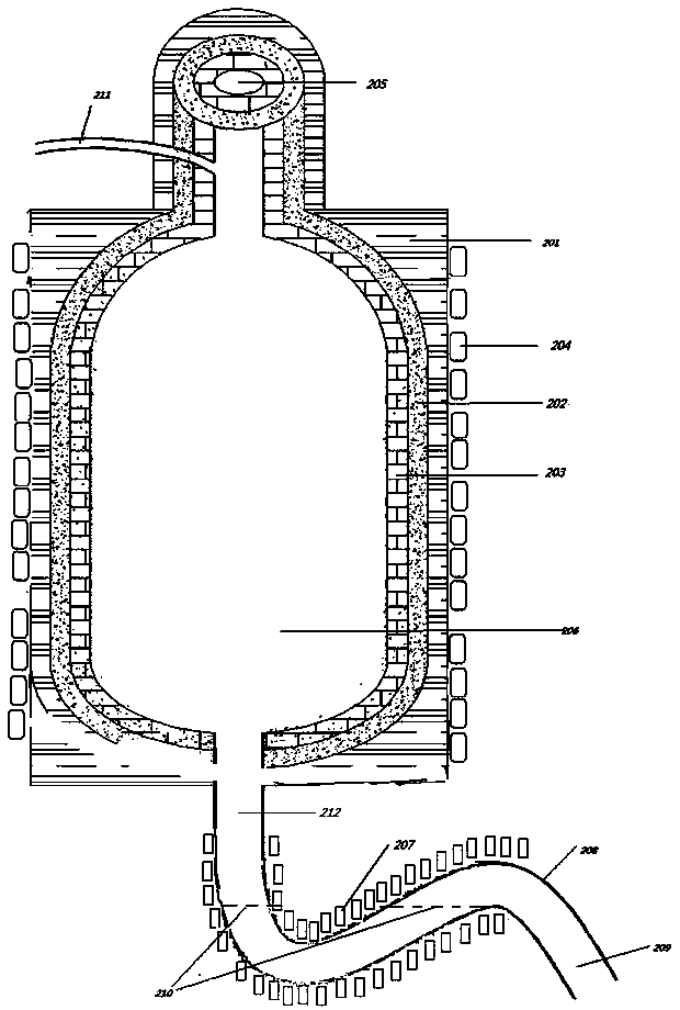
[0019] Embodiment 2: The high-temperature-resistant materials constituting the pipe walls 108 and 208 can be selected according to the smelting temperature, such as zirconia, aluminum oxide, magnesium oxide, graphite, heat-resistant steel, corundum and other materials that can withstand the corresponding temperature. The melting point of lead is 327.5 degrees Celsius, and the pipe wall material can be heat-resistant steel. When producing high-titanium slag, the melting point of titanium dioxide is about 1800 degrees Celsius, the highest melting point of iron is 1535 degrees Celsius, and the zirconia tube can withstand a temperature of 2200 degrees Celsius. When titanium slag is used, the pipe wall material is preferably zirconia.

Embodiment 3

[0020] Embodiment 3: The outer layer 201 of the furnace wall is made of high-temperature-resistant ceramic fiber board, the middle layer 202 of the furnace wall is made of aluminum oxide poured on aluminum, and the inner layer 203 of the furnace wall is made of zirconia.


PUM

PropertyMeasurementUnit
Melting pointaaaaaaaaaa

Abstract

The invention relates to a high temperature melt discharge pipe and a smelting furnace with the same. A tubular structure like a submerged bend is processed through high temperature resistant materials, a medium-frequency power supply coil winds on the outer wall of the submerged bend, and one end of the submerged bend is communicated with a discharge port arranged at the bottom of the smelting furnace. Melt deposited at the position of the submerged bend is cooled and solidified and blocks a discharge channel of the smelting furnace during smelting, and after smelting is finished, the medium-frequency power supply coil located on the outer side of the submerged bend is electrified, the condensed materials at the position of the submerged bend is subjected to heating and melting, accordingly melt in the smelting furnace is discharged through the high temperature melt discharge pipe, melt and the inner wall of the furnace do not contact with the air, and further potential safety hazards are reduced.

Description

technical field [0001] The invention relates to a high-temperature molten liquid discharge pipe in the field of metallurgy and a melting furnace with the high-temperature molten liquid discharge pipe. Background technique [0002] The intermediate frequency furnace is widely used in the field of metallurgy. It uses the electromagnetic field of the intermediate frequency frequency to heat the raw materials in the furnace body with eddy current. The metal raw materials will generate a large "eddy current" current due to cutting the magnetic force lines in the alternating magnetic field, and then generate heat and melt. . However, in the existing intermediate frequency furnace metallurgical smelting, the smelting liquid is discharged by dumping, which is not only unsafe when pouring, but also has a large heat loss, and the smelting liquid is easily oxidized, and the furnace wall is also prone to oxidation, which shortens the service life. In the field of casting, the continu...

Claims


Application Information

Patent Timeline
IPC IPC(8): F27D3/14F27B14/18F27B14/06
Inventor 不公告发明人
Owner 四川绿冶科技有限责任公司
Why Eureka
Try Eureka