Method and device for imaging non-uniform velocity moving object by TDI (Time Delayed Integration) CCD (Charge Coupled Device)

A technology of moving objects and imaging methods, which is applied in the direction of camera equipment, image communication, color TV parts, etc., can solve problems not related to imaging technology, and achieve the effect of overcoming the change of the average gray level of the image

Active Publication Date: 2015-07-22
BAOSHAN IRON & STEEL CO LTD
View PDF7 Cites 0 Cited by
  • Summary
  • Abstract
  • Description
  • Claims
  • Application Information

AI Technical Summary

Problems solved by technology

None of these patents involves imaging technology in the case of non-uniform motion of the measured object in the visual inspection system

Method used


Image

  • Method and device for imaging non-uniform velocity moving object by TDI (Time Delayed Integration) CCD (Charge Coupled Device)
  • Method and device for imaging non-uniform velocity moving object by TDI (Time Delayed Integration) CCD (Charge Coupled Device)
  • Method and device for imaging non-uniform velocity moving object by TDI (Time Delayed Integration) CCD (Charge Coupled Device)

Examples


Embodiment Construction

[0025] The present invention will be further described below in conjunction with the accompanying drawings and specific embodiments.

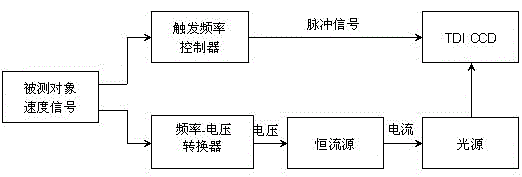
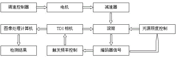
[0026] see figure 1 , an imaging method for a non-uniform moving object with a TDI CCD camera. The speed signal measured by a rotary encoder connected to the moving object is divided into two channels and sent to the light source illumination controller and the camera trigger frequency controller. The light source The illuminance controller controls the illuminance of the light source, the camera trigger frequency controller controls the exposure of the TDI CCD camera, and the scanning rate of the TDI CCD camera is synchronized with the motion rate of the measured object to complete the imaging of the measured object.

[0027] In order to ensure that the TDI CCD camera is in the push-broom process, the push-broom frequency of all levels of TDI pixels must be strictly synchronized with the speed of the rotating drum. The camera trigger frequenc...


PUM


Abstract

The invention relates to an industrial vision inspection technology, and discloses a method and device for imaging a non-uniform velocity moving object by a TDI (Time Delayed Integration) CCD (Charge Coupled Device). Speed signals measured by a rotary encoder connected with a measured moving object are divided into two paths which are respectively transmitted to a light source illuminance controller and a camera flipping frequency controller, the light source illuminance controller is used for controlling the illuminance of the light source, the camera flipping frequency controller is used for controlling the exposure of the TDI CCD, the line sweeping speed rate of the CCD and the movement speed rate of the measured object are the same so as to complete the imaging of the measured object. The light source illuminance controller converts pulse frequency signals into voltage signals, the voltage signals control a constant current source so as to further output current to an LED (Light Emitting Diode) light source, so that the illuminance of the light source is adjusted. According to the method and the device, the measured object can be clearly imaged and an image with a uniform gray level can be obtained under the condition of non-uniform movement.

Description

technical field [0001] The invention relates to industrial visual inspection technology, in particular to an imaging method and device for a TDI CCD camera to a non-uniform moving object. Background technique [0002] TDI camera is a new technology developed in recent years, and TDI (Time Delayed Integration) CCD is a new type of photoelectric sensor developed in recent years. TDI-CCD is based on multiple exposures to the same target. Through the method of delay integration, the collection of light energy is greatly increased. Compared with the general linear array CCD, it has the advantages of high responsivity and wide dynamic range. The CCD chip of the TDI camera uses time-delay integration technology to expose the same target multiple times, so that the obtained image signal has high sensitivity and signal-to-noise ratio. It is this advantage that makes TDI cameras widely used in aerospace remote sensing and telemetry and other fields. [0003] In order to meet the...

Claims


Application Information

Patent Timeline
Patent Type & Authority Patents(China)
IPC IPC(8): H04N5/235G01C11/02
Inventor 彭铁根杨水山何永辉宗德祥石桂芬梁爽
Owner BAOSHAN IRON & STEEL CO LTD
Why Eureka
Try Eureka