Light source strobe control method in time delayed and integration (TDI) charge couple device (CCD) uniform imaging under the condition of non-uniform motion

A motion situation, stroboscopic control technology, applied in optics, image communication, color TV components and other directions, can solve problems such as light source control issues that are not involved

Active Publication Date: 2013-06-05
BAOSHAN IRON & STEEL CO LTD
View PDF8 Cites 22 Cited by
  • Summary
  • Abstract
  • Description
  • Claims
  • Application Information

AI Technical Summary

Problems solved by technology

[0012] However, none of the above-mentioned patents involves the control of the light source when the measured object is uniformly imaged at a non-uniform speed in the visual inspection system.

Method used


Image

  • Light source strobe control method in time delayed and integration (TDI) charge couple device (CCD) uniform imaging under the condition of non-uniform motion
  • Light source strobe control method in time delayed and integration (TDI) charge couple device (CCD) uniform imaging under the condition of non-uniform motion
  • Light source strobe control method in time delayed and integration (TDI) charge couple device (CCD) uniform imaging under the condition of non-uniform motion

Examples


Embodiment Construction

[0044] The present invention will be further described below in conjunction with the accompanying drawings and embodiments.

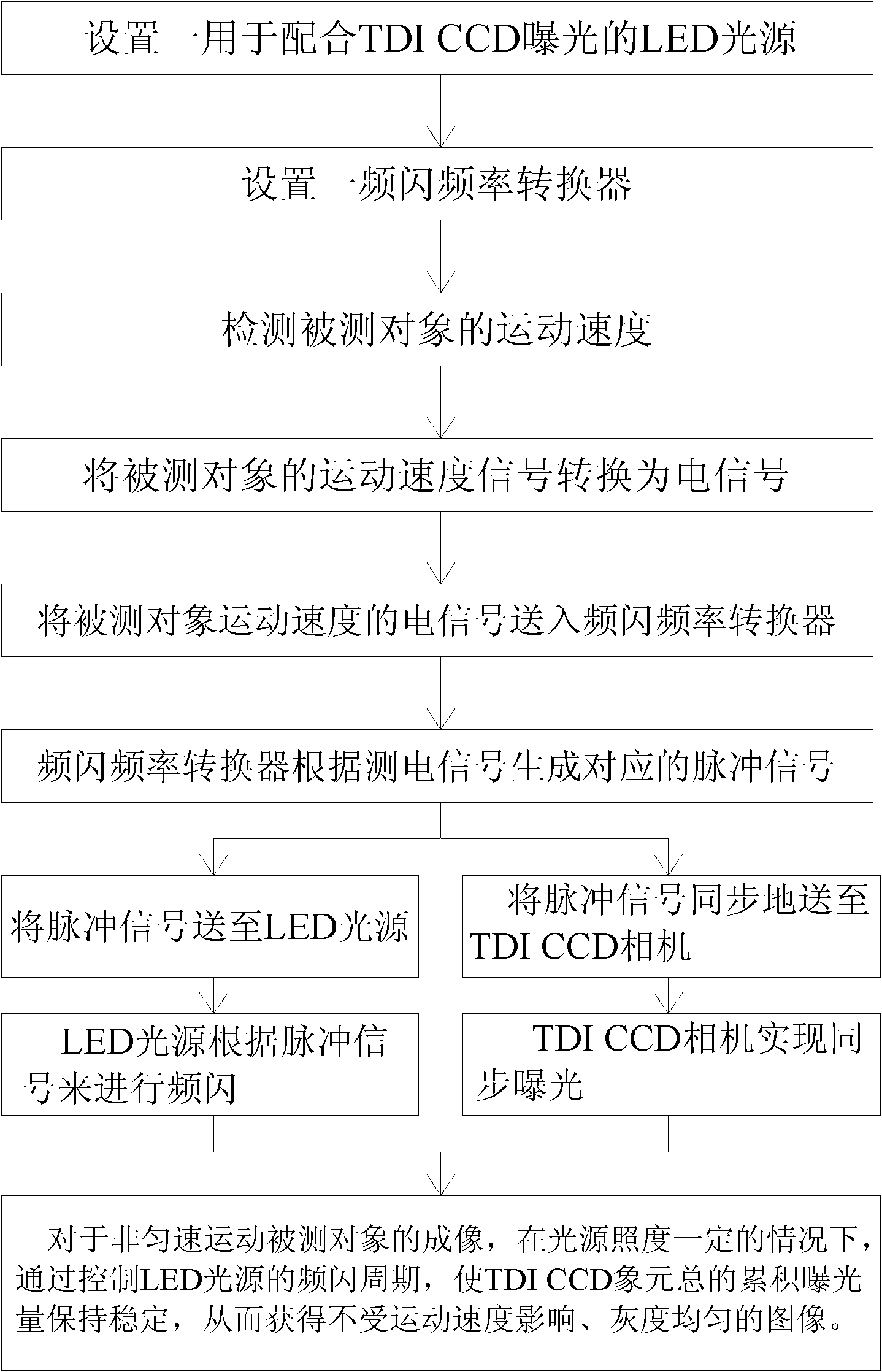
[0045] figure 1 Among them, the technical solution of the present invention includes a non-uniform moving object under test and a TDI CCD camera, the TDI CCD camera is N-level, triggers a light source for exposure after every N encoder signals, and is characterized in that the The light source stroboscopic control method at least includes the following steps:

[0046] A. Set up an LED light source for TDI CCD exposure. The LED light source has a nanosecond response speed, and its strobe can be controlled by a pulse signal;

[0047] B. Set a strobe frequency converter, which can convert the motion speed signal of the measured object into a strobe frequency signal, and use this signal to control the on and off frequency of the LED light source and the synchronous exposure of the TDI CCD camera;

[0048] C. Detect the movement speed of the measured obje...


PUM


Abstract

The invention discloses a light source strobe control method in time delayed and integration (TDI) charge couple device (CCD) uniform imaging under the condition of non-uniform motion, and belongs to the field of control. Light source strobe control equipment comprises a test object which moves non-uniformly and a TDI CCD camera. The light source strobe control method includes the steps: a light-emitting diode (LED) light source in conjunction with TDI CCD exposure is disposed, a strobe frequency converter for converting moving speed signals into strobe frequency signals is disposed, and the strobe frequency is used for controlling starting and closing frequency of the LED light source and controlling synchronous exposure of the TDI CCD. Moving speed of the test object is detected, synchronous control of the strobe cycle of the light source is realized according to the moving speed of the test object, total exposure time of the TDI CCD camera in the sweeping cycle is regulated, and thus image of uniform gray gradation of the test object which moves non-uniformly is output.

Description

technical field [0001] The invention belongs to the field of measurement control, in particular to an exposure control method for ensuring the imaging effect of a camera. Background technique [0002] Digital cameras are being used more and more in visual inspection systems for the surface quality of strips (such as strip steel, glass, cloth, etc.) that require high speed and high resolution. [0003] A CCD (Charge Couple Device, Charge Coupled Device) camera, as a front-end sensor for photodetection image acquisition, has long been adopted by people. [0004] A general-purpose CCD camera uses the CCD as the photosensitive surface, uses the CCD to perform self-scanning under the drive of the set drive pulse, decomposes the image distributed according to the space into timing signals corresponding to the pixels, and then outputs the video that meets the specified format in a certain way image signal. [0005] TDI (Time Delayed and Integration) CCD is a new type of photoelec...

Claims


Application Information

Patent Timeline
Patent Type & Authority Applications(China)
IPC IPC(8): H04N5/235G01N21/89G03B15/05
Inventor 彭铁根王康健何永辉宗德祥石桂芬陆丽华
Owner BAOSHAN IRON & STEEL CO LTD
Why Eureka
Try Eureka