High-ratio power battery liquid-cooling system
A power battery, high-rate technology, applied in secondary batteries, battery pack components, circuits, etc., can solve problems such as reduced cooling efficiency, battery system capacity limitations, and inability to meet battery system operating requirements, and achieve mileage and battery life. Longer life and easier installation and connection
- Summary
- Abstract
- Description
- Claims
- Application Information
AI Technical Summary
Problems solved by technology
Method used
Image

Examples
Embodiment 1
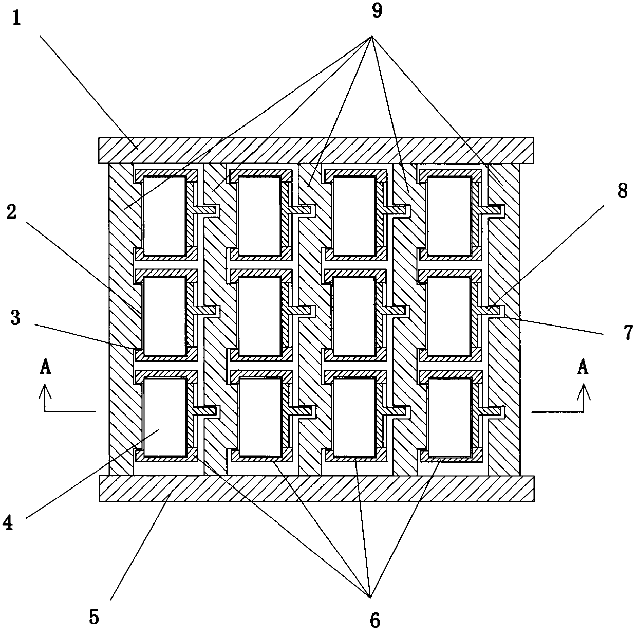
[0032] The top view plan layout of a liquid cooling system for a high-rate battery is as follows: figure 1 As shown, the system includes a battery 4, a module frame 6, a liquid cooling wall 9 and other components. The battery 4 is placed in the module rack 6 . The module frame 6 is placed in a space surrounded by the liquid cooling wall 9, the shroud 1 and the liquid collecting plate 5. The module racks 6 are arranged in four rows, each row has three module racks 6, and a total of 12 module racks 6 are placed in the entire liquid cooling system. Each row of module racks 6 is separated by a liquid cooling wall 9 . from figure 1 It can be seen from the figure that both sides of each module frame 6 are liquid-cooled walls 9.
[0033] Such as figure 1 , Image 6 As shown: the interior of the liquid cooling wall 9 is provided with a rectangular liquid cooling tube 15, and part of the wall surface of the rectangular liquid cooling tube 15 protrudes from the wall surface of the...
Embodiment 2
[0045] The difference between this example and embodiment 1 is: a small liquid cold plate 16 is installed on the module frame 6, see Figure 5 , replacing the T-shaped heat conducting plate 8 in Example 1. One side of the liquid cooling plate 16 is in contact with the battery 4 in the module frame 6 . The liquid cooling plate 16 is provided with a liquid cooling tube, and the liquid cooling tube in the liquid cooling plate can communicate with the liquid cooling tube in the liquid cooling wall through the hose 17 and the joint 18, as long as the corresponding positions on the liquid cooling wall 9 are opened. It is good to connect the hole. In this way, the liquid coolant in the liquid cooling wall 9 can flow through the liquid cooling plate 16 to take away part of the heat from the battery 4 .
[0046] In this example, the liquid cooling wall 9 does not need to be slotted, which can make the arrangement of the liquid cooling tubes in the liquid cooling wall 9 more flexible, ...
PUM
 Abstract
Description
Claims
Application Information
 - Generate Ideas
- Intellectual Property
- Life Sciences
- Materials
- Tech Scout
- Unparalleled Data Quality
- Higher Quality Content
- 60% Fewer Hallucinations
Browse by: Latest US Patents, China's latest patents, Technical Efficacy Thesaurus, Application Domain, Technology Topic, Popular Technical Reports.
© 2025 PatSnap. All rights reserved.Legal|Privacy policy|Modern Slavery Act Transparency Statement|Sitemap|About US| Contact US: help@patsnap.com