

Medical guide wire
A technology of guide wire and guide wire head, applied in the field of medical devices, can solve problems such as cavity perforation, and achieve the effect of reducing the risk of cavity perforation and the risk of clinical operation
- Summary
- Abstract
- Description
- Claims
- Application Information
AI Technical Summary
Problems solved by technology
Method used
Image

Examples
Embodiment 1
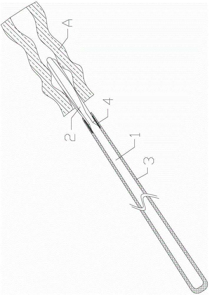
[0047] combine Figure 1-7
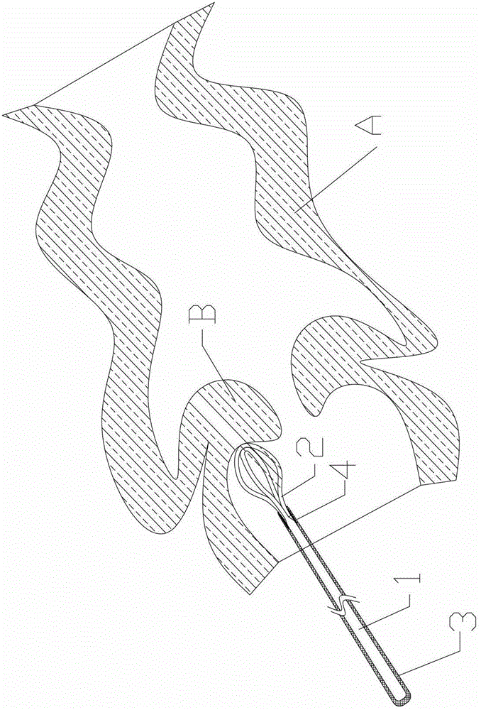
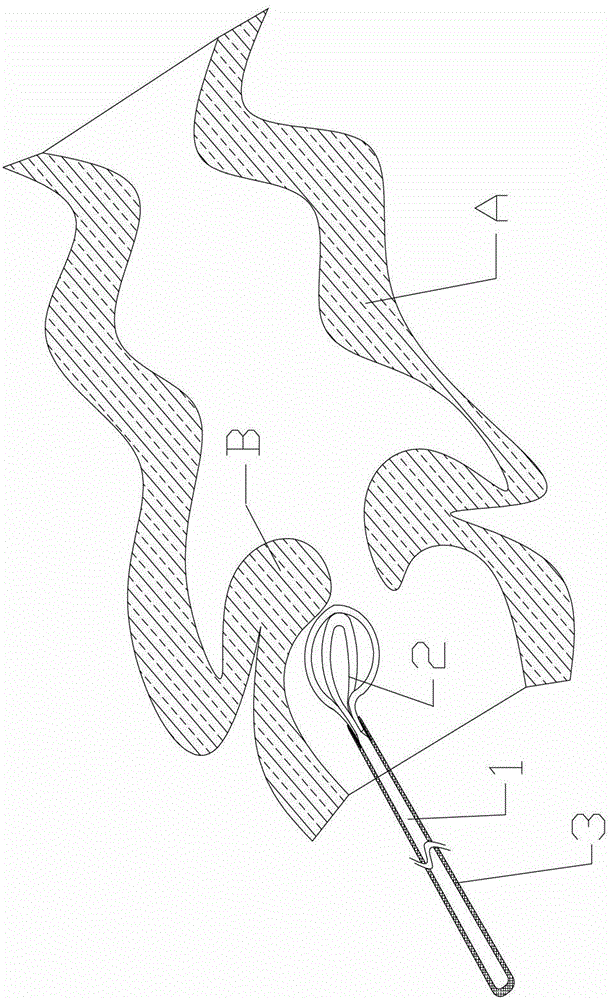
[0048] A medical guide wire includes a flexible long mandrel 1, a guide wire head 2 located at the head of the mandrel 1, and a coating 3 made of a flexible material wrapped around the mandrel 1, the guide wire The head end 2 is hollow and spindle-shaped with a smooth surface. The guide wire head end 2 is composed of flexible strip-shaped petals, and the strip-shaped petals are arranged along the axial direction. The cladding layer 3 can be made of polymer material, or other materials with elasticity and low coefficient of friction, such as a spring tube. The existence of the coating layer 3 is beneficial to reduce the resistance of pushing the guide wire, so that the doctor can obtain a better hand feeling.
[0049] The guide wire tip 2 is fixedly connected to the mandrel 1 through the connecting piece 4 , and the coating layer 3 covers the connecting portion between the guide wire tip 2 and the mandrel 1 .
[0050] The strip-shaped flap is cov...
Embodiment 2
[0061] combine Figure 8 , 9
[0062] The difference between this embodiment and Embodiment 1 lies in the specific structure of the head end. The specific structure is as follows: Figure 9 As shown, the strip-shaped flap is a metal lath 2B, the guide wire tip 2 has at least two metal laths 2B, all the metal laths 2B radiate outward from the same center C, the metal lath 2B is integrated with the center C, and the metal plate The free end of the bar 2B is fixed to the mandrel 1 . The metal lath 2B is stamped into a smooth spindle shape, and the center C is the part in contact with the cavity A. The metal laths 2B are evenly distributed along the center C. The connector 4 is a sleeve, and the mandrel 1 and the metal lath 2B are both sleeved in the sleeve, and the sleeve fixes the mandrel 1 and the metal lath 2B by welding or bonding. All the other structures are the same as in Example 1.
[0063] In this embodiment, the head end of the guide wire is formed by punching th...
Embodiment 3
[0066] Figure 10-13
[0067] The difference between this embodiment and Embodiment 1 lies in the specific structure of the head end. The specific structure is as follows: the strip-shaped flap is a metal wire 2C, the guide wire head end 2 includes at least two metal wires 2C, the metal wires 2C arch outwards to form a spindle, and one end of each metal wire 2C is connected to the mandrel 1 Fixed connection, the other end is fixed at one point with other metal wire 2C, and the fixing point of metal wire 2C is smooth. All the other structures are the same as in Example 1.
[0068] The metal wires 2C are fixed by welding or bonding. The fixed point becomes a smooth front end after grinding, and the fixed point is used as the part in contact with the cavity A.
[0069] After the metal wires 2C are fixed by welding or bonding, the fixing points need to be polished to obtain a smooth front end, so as to avoid damage to the cavity wall.
[0070] Such as Figure 10 and 11 Show...
PUM
 Abstract
Description
Claims
Application Information