
Surface protection film and optical component attached therewith

A technology for surface protection films and optical components, which is applied to optical components, optics, film/sheet adhesives, etc., can solve problems such as circuit component damage and liquid crystal molecular orientation damage, and achieve improved production performance and yield , no aging effect

Active Publication Date: 2013-11-06
FUJIMORI KOGYO CO LTD
View PDF7 Cites 18 Cited by
  • Summary
  • Abstract
  • Description
  • Claims
  • Application Information

AI Technical Summary

Problems solved by technology

[0004] In recent years, in the production process of liquid crystal display panels, due to the peeling voltage generated when the surface protection film bonded on the optical film is peeled off, although the number of cases is small, the drive for controlling the liquid crystal display screen also occurs. Phenomenon in which circuit components such as ICs are destroyed, and phenomenon in which the alignment of liquid crystal molecules is damaged

Method used


Image

  • Surface protection film and optical component attached therewith
  • Surface protection film and optical component attached therewith
  • Surface protection film and optical component attached therewith

Examples


Embodiment 1)

[0087] (Preparation of Adhesive Composition)

[0088] Add 90 parts by weight of 2-ethylhexyl acrylate, 10 parts by weight of methoxypolyethylene glycol (400) monomethacrylate, acrylic acid 3 parts by weight of 2-hydroxyethyl ester, 0.2 parts by weight of 2,2'-azobisisobutyronitrile as a polymerization initiator, and 154 parts by weight of ethyl acetate were heated up to 65° C. while stirring the content while introducing nitrogen gas. Furthermore, a polymerization reaction was carried out at a temperature of about 65° C. for 6 hours to obtain the adhesive composition of Example 1 (40% solid content) formed of an acrylic polymer containing a polyoxyalkylene group.

[0089] (Preparation of surface protection film)

[0090] 3 parts by weight of addition reaction silicone (manufactured by Toray Dow Corning Co., Ltd., trade name: SRX-345) and polyether-modified silicone (manufactured by Toray Dow Corning Co., Ltd., trade name: SH8400) 0.1 parts by weight, 97 parts by weight of a ...

Embodiment 2)

[0092] 100 parts by weight of the adhesive composition of Example 1 and 0.1 part by weight of lithium perchlorate as an antistatic agent were stirred and mixed to prepare the adhesive composition of Example 2 containing an antistatic agent.

[0093] Except having used the adhesive composition of Example 2 instead of the adhesive composition of Example 1, it carried out similarly to Example 1, and obtained the surface protection film of Example 2.

Embodiment 3)

[0095] Stir and mix 100 parts by weight of the adhesive composition of Example 1 and 1.5 parts by weight of lithium bis(trifluoromethanesulfonyl)imide as an antistatic agent to prepare the adhesive combination of Example 3 with an antistatic agent thing.

[0096] Except having used the adhesive composition of Example 3 instead of the adhesive composition of Example 1, it carried out similarly to Example 1, and obtained the surface protection film of Example 3.


PUM


Abstract

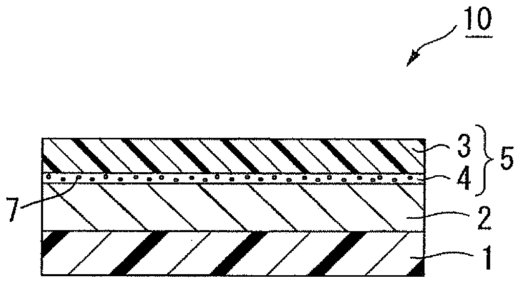
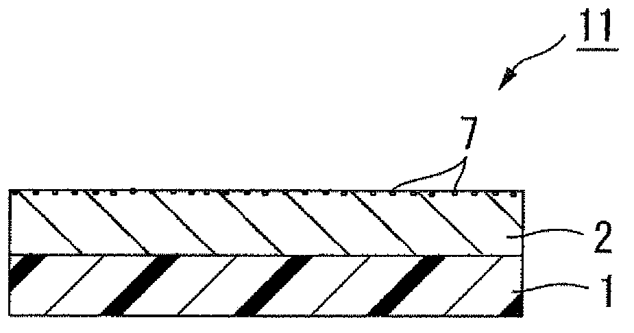
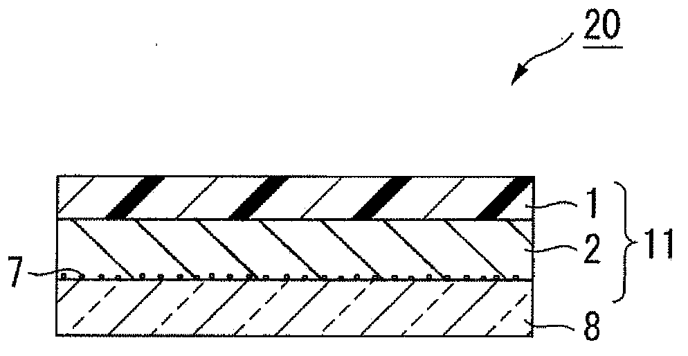
The invention provides a surface protection film and an optical component attached therewith. Specifically, a surface protection film which causes less pollution to an object the film is attached to, suffers no time degradation, and has excellent stripping-prevention electrified performance, and an optical component using the surface protection film are provided. In the surface protection film 10 where an adhesive layer 2 is formed on one surface of a transparent base material film 1 and a stripping film 5 is attached to the adhesive layer 2, the stripping film 5 is obtained by laminating a stripping agent layer 4 on one surface of a resin film 3 and the stripping agent layer 4 comprises stripping agent with dimethyl polysiloxane as the main component and silicone compound 7 which is liquid at the temperature of 20 DEG C. The adhesive layer 2 is formed by (meth)acrylic acid polymer obtained through copolymerization or blending of compound containing polyoxyalkylene groups and contains antistatic agent.

Description

technical field [0001] The present invention relates to a surface protection film to be bonded to the surface of an optical member (hereinafter also referred to as an optical film) such as a polarizing plate, a retardation plate, and a lens film for a display. The present invention provides a surface protection film with little contamination to an adherend, a surface protection film that does not deteriorate with time and has excellent anti-peeling electrification performance, and an optical component using the surface protection film. Background technique [0002] When manufacturing and shipping optical products such as displays using optical films such as polarizing plates, retardation plates, lens films for displays, antireflection films, hard coat films, transparent conductive films for touch panels, etc. A surface protective film is pasted on the surface to prevent contamination or damage to the surface in subsequent processes. In the visual inspection during the produ...

Claims


Application Information

Patent Timeline
IPC IPC(8): C09J7/02C09J133/08C09D183/04C09D183/12B32B7/06C09J11/04C09J133/00C09J201/00G02B1/10G02B1/116G02B5/30
CPCC09D5/20C09J7/22C09J7/38C09J7/401C09J133/04C09J2301/16C09J2301/302C09J2301/312C09J2301/41G02B5/00G02B5/005
Inventor 小林弘幸春日充远藤佳子林益史
Owner FUJIMORI KOGYO CO LTD
Learn More