Hydraulic control system with load pressure reduction device and hydraulic valve set therefor

A technology of control device and pressure, applied in the direction of fluid pressure actuation device, fluid pressure actuation system test, servo motor assembly, etc. Design simple effects

Active Publication Date: 2013-11-06
ROBERT BOSCH GMBH
View PDF8 Cites 11 Cited by
  • Summary
  • Abstract
  • Description
  • Claims
  • Application Information

AI Technical Summary

Problems solved by technology

[0006] The disadvantage of this solution is also: there is still the problem of permanent leakage flow caused by the load signal line, this leakage flow has to be compensated by the hydraulic pump
This prevents full utilization of the pump power and reduces the power

Method used


Image

  • Hydraulic control system with load pressure reduction device and hydraulic valve set therefor
  • Hydraulic control system with load pressure reduction device and hydraulic valve set therefor
  • Hydraulic control system with load pressure reduction device and hydraulic valve set therefor

Examples


Embodiment Construction

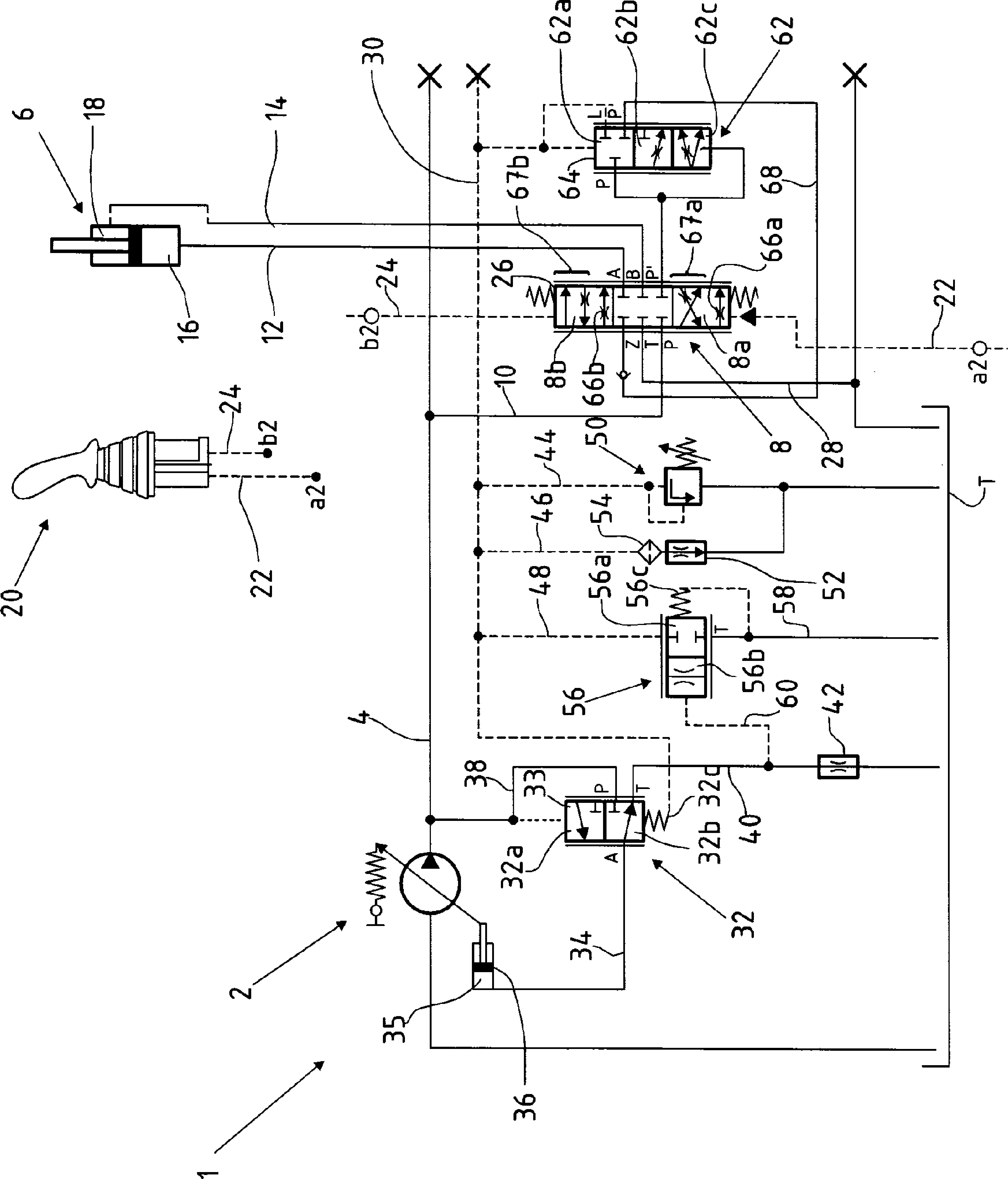
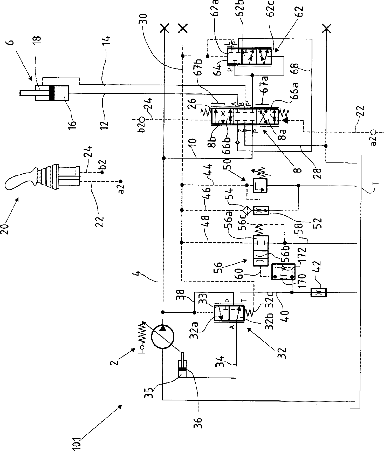
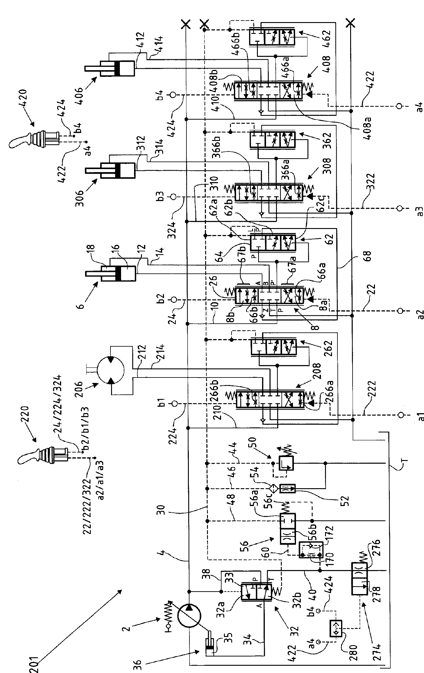
[0083] according to figure 1 , the hydraulic control unit 1 of the compact excavator has a hydraulic pump 2 with an adjustable delivery volume. The preparation line 4 through the hydraulic pump 2 can feed several hydraulic consumers (see image 3 ) to provide the pressure medium. according to figure 1 , of these hydraulic consumers only the first hydraulic consumer 6 is shown, which is formed by a synchronized cylinder with a one-sided piston rod for actuating the boom of the micro-excavator. In order to actuate the first hydraulic consumer 6 , a control valve 8 is assigned to said consumer. In this case, the control valve 8 is designed as a 6 / 3 proportional directional valve (6 / 3 proportional directional valve) with a spring-centered blocking position. The control valve 8 is connected via a working line 10 to the auxiliary line 4 of the hydraulic pump 2 and via working lines 12 , 14 to the working chambers 16 , 18 of the first hydraulic consumer 6 . For actuating the con...


PUM


Abstract

The hydraulic control system has an adjustable hydraulic pump (2) via which the pressure medium is supplied to hydraulic load. A pumping controller (32) is provided for controlling the volumetric flow of an adjuster (36) of the hydraulic pump in dependence of supply pressure or highest load pressure of the hydraulic load. A pressure reduction device (56) for high load pressure is more adjusted in dependence of controlled volumetric flow.

Description

technical field [0001] The invention relates to a hydraulic control device with a load pressure reduction device according to the preamble of claim 1 and a hydraulic control device for a control device of this type according to the preamble of claim 15 valve group. Background technique [0002] In working machines, especially in the case of mobile and compact designs such as compact or mini excavators, backhoe loaders or telescopic loaders, hydraulic pumps preferably provide an adjustable delivery to hydraulic consumers volume. In this case, the volume flow is distributed via control valves which must ensure a harmonious movement sequence even when operating several consumers. In load-sensing systems, the regulation of the delivery volume flow of the hydraulic pump is done via a pump regulator, which communicates to the pump on the one hand the highest load pressure of the consumer and, on the other hand, the ready line pressure of the hydraulic pump Regulator. In order ...

Claims


Application Information

Patent Timeline
Patent Type & Authority Applications(China)
IPC IPC(8): F15B11/16F15B13/06
CPCF15B2211/20553F15B2211/605F15B11/165F15B11/16F15B2211/654E02F3/325E02F9/2232E02F9/2285E02F9/2296E02F9/22F15B5/00F15B19/00
Inventor W.考斯
Owner ROBERT BOSCH GMBH
Why Eureka
Try Eureka