
Method of transporting liquid drops by micro-fluidic chip

A microfluidic chip and droplet technology, applied in the field of biomedicine, can solve the problems of low reusability, easy blockage of micropipes, complicated manufacturing process of micropipes, etc., and achieve the effect of reducing the driving voltage of the chip

Inactive Publication Date: 2013-11-13
SUZHOU UNIV
View PDF2 Cites 32 Cited by
  • Summary
  • Abstract
  • Description
  • Claims
  • Application Information

AI Technical Summary

Problems solved by technology

Among many methods of driving micro-droplets, the traditional method is to realize the generation and control of micro-droplets in micro-channels, but the manufacturing process of micro-channels is very complicated, and micro-channels are easily blocked, and the reusability is not high. Requires complex peripherals to drive

Method used


Image

  • Method of transporting liquid drops by micro-fluidic chip
  • Method of transporting liquid drops by micro-fluidic chip
  • Method of transporting liquid drops by micro-fluidic chip

Examples


Embodiment Construction

[0034] The embodiment of the present invention discloses a method for transporting droplets by a microfluidic chip, including:

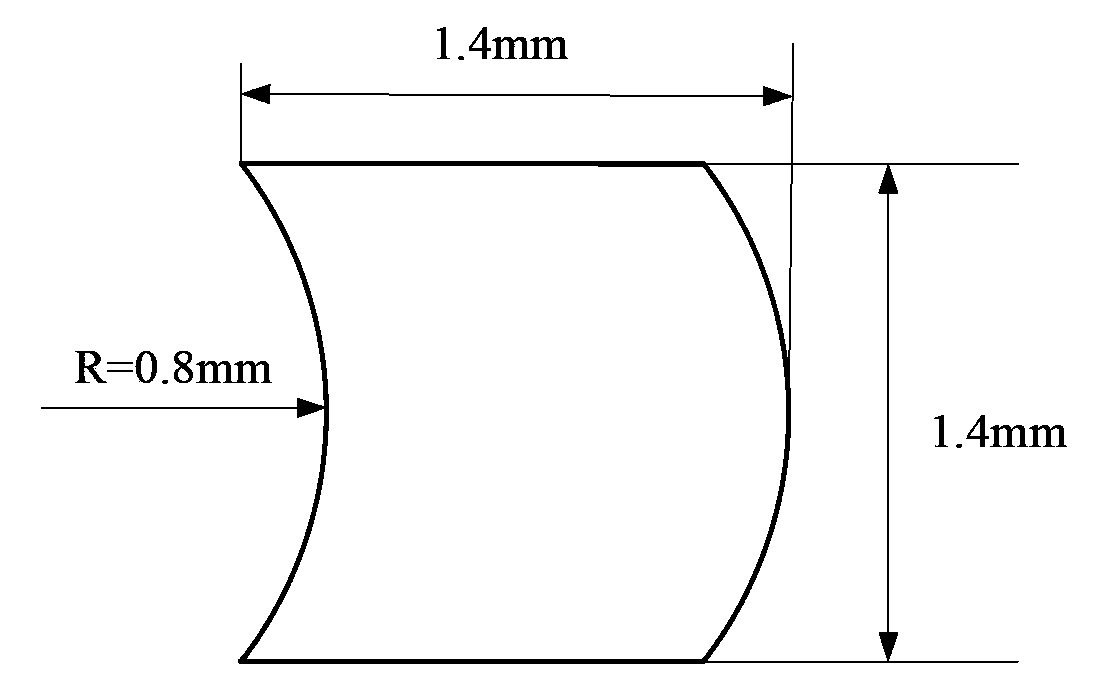
[0035] s1. Provide a microfluidic chip. The microfluidic chip includes drive electrodes arranged in an array. The drive electrodes are half-moon-shaped. In the droplet transport direction, one edge of the drive electrodes is a convex arc shape, the other side edge is a concave arc shape, and the concavity and convexity between adjacent electrodes are opposite;

[0036] s2. Applying a potential of 32V to 60V between adjacent driving electrodes to drive the movement of the liquid droplets on the driving electrodes.

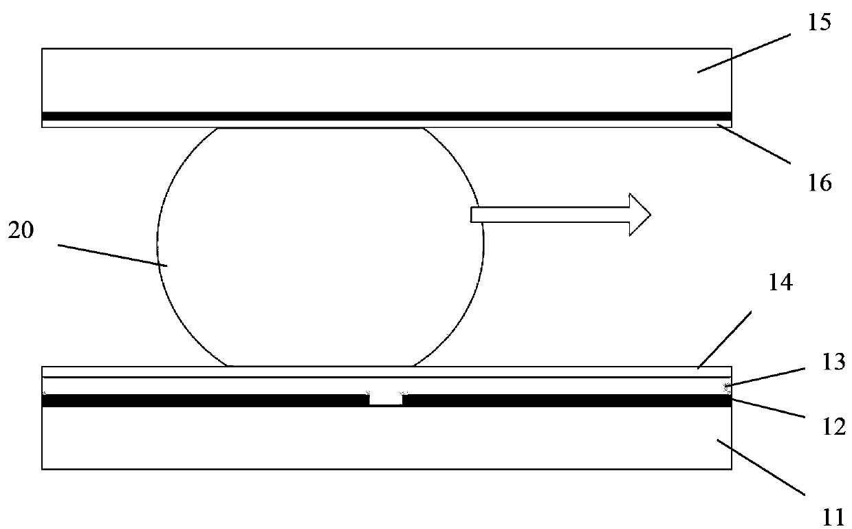
[0037] Preferably, in the above-mentioned method for transporting droplets 20 by a microfluidic chip, the microfluidic chip includes a lower pole plate and an upper pole plate oppositely arranged, and the lower pole plate includes a first substrate 11 and The driving electrode 12, the dielectric layer 13 and the first water-repellent laye...


PUM


Abstract

The invention discloses a method of transporting liquid drops by a micro-fluidic chip. The method comprises following steps: step one, a micro-fluidic chip is provided, the micro-fluidic chip comprises array-arranged driving electrodes, the driving electrodes are in half-moon shapes, in the fluid drop transportation direction, one edge of each electrode is in a convex arc shape, the other edge of each electrode is in a concave arc shape, and the convex arc is opposite to the concave arc between two neighbored electrodes; step two, an electric potential between 32 V and 60 V is exerted between the neighbored driving electrodes to drive the liquid drops on the driving electrodes to move. The method of transporting liquid drops by a micro-fluidic chip aims to reduce the driving voltage of a digital micro-fluidic chip, so the electric field strength of the chip is reduced, damages to the biological activity organisms contained in the liquid drops are avoided, and the use efficiency of the digital micro-fluidic chip is improved at the same time.

Description

technical field [0001] The invention belongs to the technical field of biomedicine, and in particular relates to a method for transporting droplets by a microfluidic chip. Background technique [0002] The research on microfluidic chips began in the early 1990s. Manz and Harrison first carried out early research on chip electrophoresis, first proposed basic concepts such as micro-total analysis systems, and positioned microfluidic chips as generally having a thickness of no more than 5 mm, and a planar chip with an area of ​​no more than a dozen square centimeters. Due to its many advantages, the dielectric wetting effect is increasingly used to manipulate micro-droplets in digital microfluidic chips. [0003] In the past two decades, digital microfluidic chips have shown a vigorous development trend in laboratory research and industrial applications, especially digital microfluidic chips based on micro-droplet manipulation have made great progress. The volume of the manip...

Claims


Application Information

Patent Timeline
IPC IPC(8): B01L3/00
Inventor 陈立国许晓威
Owner SUZHOU UNIV
Learn More