Micro-fluidic chip clamp

A technology of microfluidic chips and fixtures, which can be used in supporting appliances, laboratory appliances, chemical instruments and methods, etc., and can solve problems such as troublesome operation, overturning, and position deviation.

Inactive Publication Date: 2013-11-13
苏州扬清芯片科技有限公司
View PDF1 Cites 40 Cited by
  • Summary
  • Abstract
  • Description
  • Claims
  • Application Information

AI Technical Summary

Problems solved by technology

Although the above method is low in material cost, it is cumbersome to operate, and the sticking process is prone to blockage, and the weight of the catheter often makes the placement of the chip very unstable, and it is easy to be affected by the catheter and cause the position to shift or even fall over.

Method used


Image

  • Micro-fluidic chip clamp
  • Micro-fluidic chip clamp

Examples


Embodiment 1

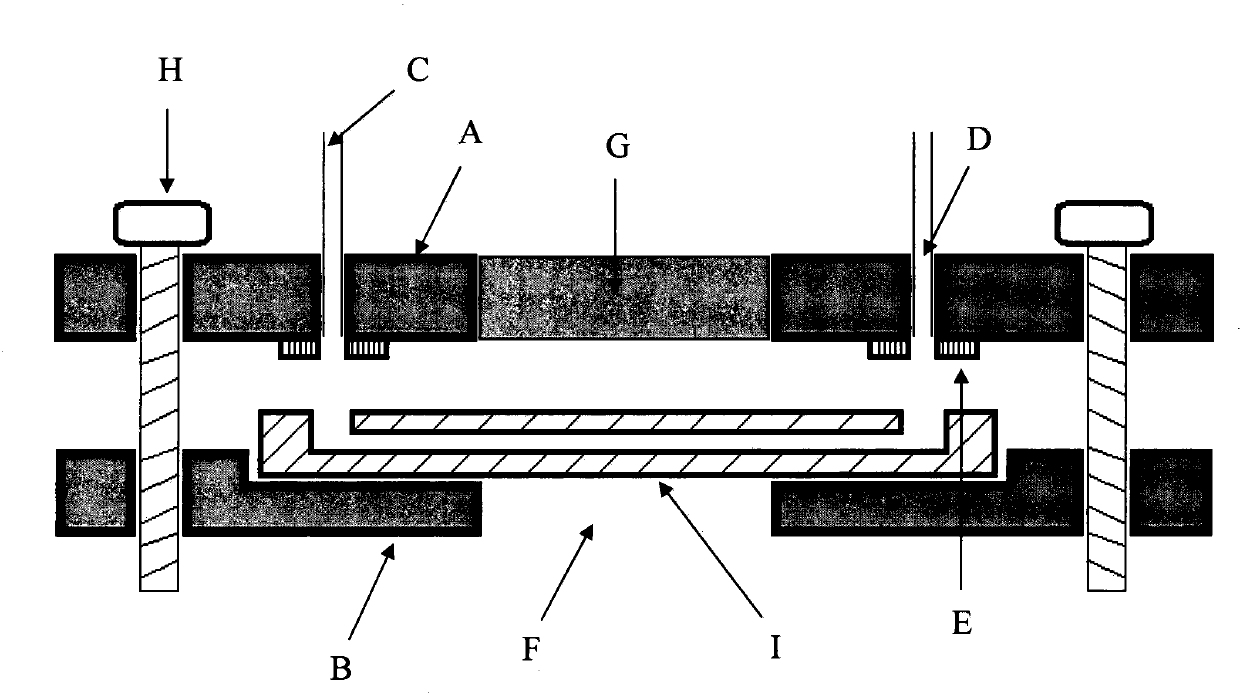
[0018] Embodiment 1 A kind of microfluidic chip fixture

[0019] A microfluidic chip fixture, made of ABS plastic injection molding, its structure is as follows figure 1 As shown, the fixture is composed of upper and lower splints A and B, wherein the upper splint is processed with fastening threaded holes, conduit joints D, elastic gaskets E, and observation windows that can be embedded with optical devices G; the lower splint is processed with tight Solid threaded hole, chip fixing groove, hollow observation window F; when in use, place the microfluidic chip I in the two splints, align the sample pool of the chip with the elastic gasket or O-ring, and tighten it Screw H can tightly clamp the microfluidic chip between the upper and lower splints. On the one hand, it can ensure the immobilization of the microfluidic chip. On the other hand, after inserting the catheter into the catheter connector of the splint, it can be easily realized The connection between microfluidic chi...

Embodiment 2

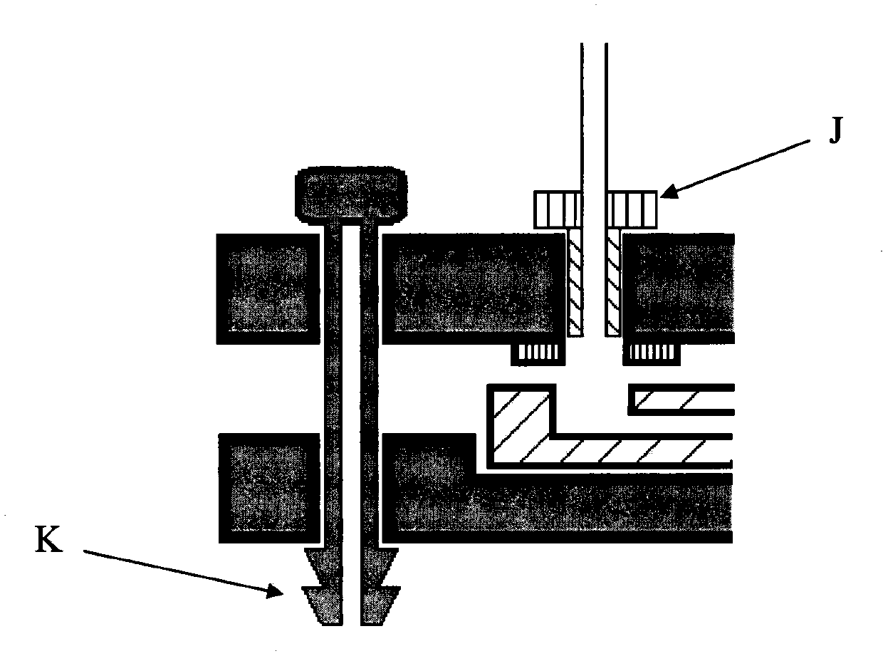
[0020] Example 2 A microfluidic chip fixture based on a hook structure

[0021] This embodiment provides a microfluidic chip fixture based on a hook structure, which is different from the fixture described in Example 1 in that the fixture provided in this embodiment uses a hook-type fastening device to fix the upper and lower splints In addition, a threaded catheter connector is used to connect the catheter to the chip.

[0022] For the hook-type structure of the splint on the microfluidic chip fixture and the structure of the threaded catheter connector, see figure 2 . When in use, the microfluidic chip I is placed in the two splints. After alignment, the microfluidic chip can be tightly clamped between the upper and lower splints only by using the hook structure. On the one hand, it can ensure that the microfluidic chip On the other hand, after screwing the threaded catheter connector with the catheter into the splint, the connection between the microfluidic chip and the ...


PUM


Abstract

Aiming at the problems, the invention provides a micro-fluidic chip clamp. The micro-fluidic chip clamp is characterized by guaranteeing the immobilization of a micro-fluidic chip in a use process and supplying a fluid inlet and a fluid outlet. The micro-fluidic chip clamp consists of two clamping plates; the micro-fluidic chip is pressed and fixed between the two clamping plates through screws or clamping hook structures; a plurality of conduit connection openings and a plurality of chip sample pool connection openings are formed in the clamping plates and are used for connecting an external fluid control system and the micro-fluidic chip.

Description

technical field [0001] The invention relates to the field of microfluidic chips, in particular to a fixture for a microfluidic chip. Background technique [0002] Microfluidic chip technology has been widely researched and applied in biology, chemistry, medicine and other fields. In the practical application of microfluidic chips, the fixing device and fluid joint device of the microfluidic chip are devices that connect the internal channels of the microfluidic chip and the fluid pipelines such as external pump valves, and play a very important role. However, at present, in the field of microfluidic laboratories, it is often used to directly insert the hard catheter into the sample hole of the elastic polydimethylsiloxane (PDMS) microfluidic chip, or stick the catheter to the hard Fluid inlet and outlet for plastic or glass chips. Although the above-mentioned method has low material cost, it is cumbersome to operate, and the sticking process is prone to blockage, and the w...

Claims


Application Information

Patent Timeline
Patent Type & Authority Applications(China)
IPC IPC(8): B01L9/00
Inventor 叶嘉明
Owner 苏州扬清芯片科技有限公司
Why Eureka
Try Eureka