
A combined tumor pushing knife and its application method

A combined technology of tumor pushing knife, which is applied in auxiliary devices, auxiliary welding equipment, welding/cutting auxiliary equipment, etc., can solve the problems of tumor pushing knife stuck, unable to open, inconvenient, etc., so as to improve the degree of freedom and avoid The effect of interference jamming and convenient operation and use

Active Publication Date: 2016-05-04
CHANGZHOU RUITAI ENG MASCH CO LTD +1
View PDF8 Cites 0 Cited by
  • Summary
  • Abstract
  • Description
  • Claims
  • Application Information

AI Technical Summary

Problems solved by technology

There are two major problems when adopting the design idea of ​​the existing tumor-removing knife to design a tumor-removing knife suitable for grooved rails: 1) Since the cutter body needs to have a protrusion extending downward into the groove of the grooved rail, and the grooved rail has One side of the groove is deeper than the other side relative to the rail head, so the pusher knife will be stuck due to interference and cannot be opened; 2) Need to design the pusher that fits the grooved rails on the left and right sides respectively Knives, extremely inconvenient both to make and to use

Method used


Image

  • A combined tumor pushing knife and its application method
  • A combined tumor pushing knife and its application method
  • A combined tumor pushing knife and its application method

Examples


Embodiment 1

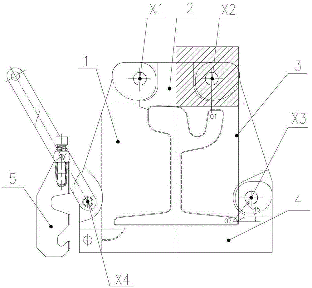
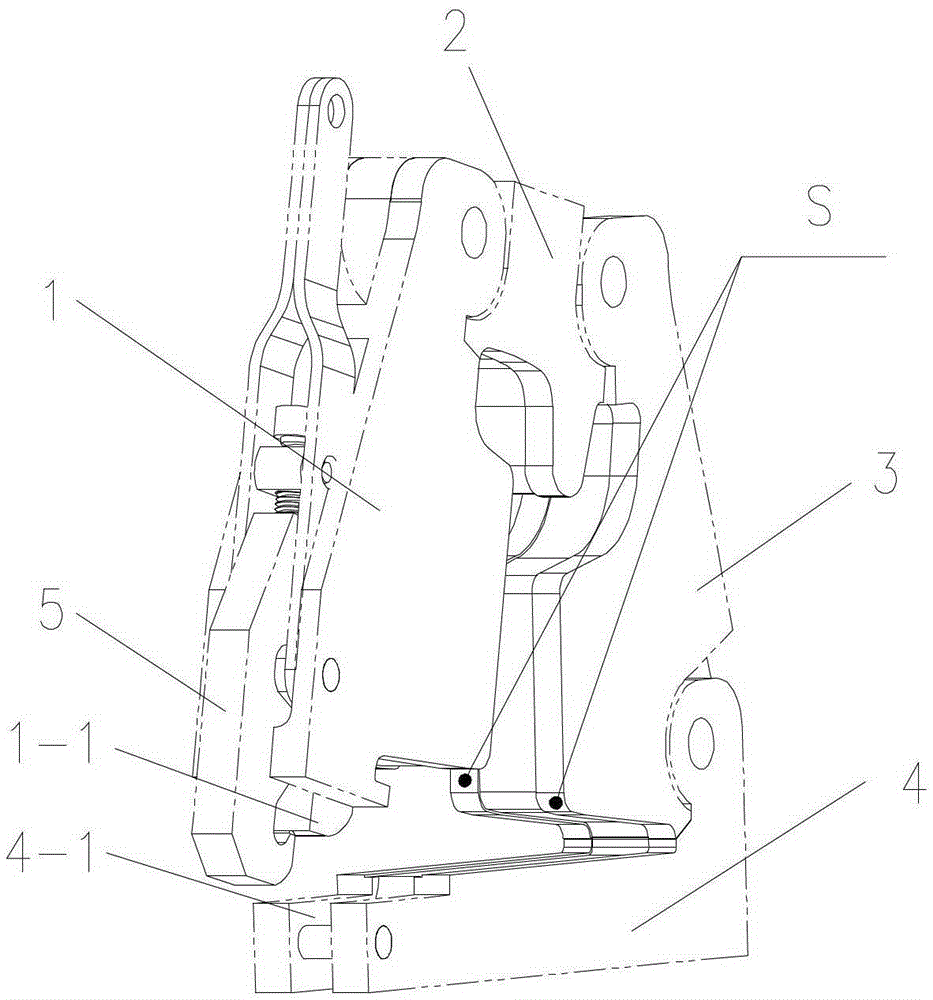
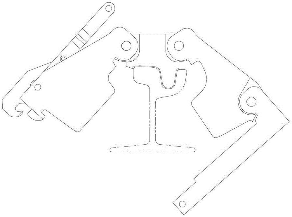
[0026] The combined tumor pushing knife of the present embodiment is as figure 1 As shown, the left cutter body 1, the upper cutter body 2, the right cutter body 3, and the lower cutter body 4 are connected in sequence. The left cutter body 1 and the upper cutter body 2 are hinged at the upper left of the envelope inner profile through the pin X1, and the locking mechanism 5 is the same as the prior art, and is hinged with the lower part of the left cutter body through the pin X4. The enveloping inner contour surrounded by the left cutter body 1, upper cutter body 2, right cutter body 3 and lower cutter body 4 basically coincides with the cross-sectional outer contour of the grooved rail. The upper cutter body 2 extends downwards to protrude into the groove of the grooved rail. The right part of the upper cutter body 2 and the upper part of the right cutter body 3 are hinged through the pin X2 at the upper right of the envelope inner profile, and the lower part of the right c...


PUM


Abstract

The invention relates to a combined overlap pushing cutter and a use method thereof, belonging to the technical field of construction of traffic facilities. The combined overlap pushing cutter comprises a left cutter body, an upper cutter body, a right cutter body, a lower cutter body and a locking mechanism, wherein the left cutter body, the upper cutter body and the right cutter body are sequentially connected; the left cutter body and the upper cutter body are hinged on the left upper side of an internal envelop profile; the locking mechanism is hinged to the lower part of the left cutter body through a pin shaft; the internal envelop profile surrounded by the left cutter body, the upper cutter body, the right cutter body and the lower cutter body is basically identical with the external profile of the cross section of a grooved rail; the right part of the upper cutter body and the upper part of the right cutter body are hinged on the right upper side of the internal envelope profile; and the lower part of the right cutter body and the right part of the lower cutter body are hinged outside the right side of the bottom edge of the internal envelop profile. According to the combined overlap pushing cutter and the use method thereof, interference and clamping stagnation can be completely avoided, the weight is effectively controlled, the manual cutter hanging and removing efficiency is greatly improved, and the overlap pushing cutter is uniform in left and right stress and is not deviated in the overlap pushing process. Furthermore, due to adoption of the double-sided cutting edge design, the requirement that overlap pushing for two grooved steel trails along one line is met, the strength deformation of a matrix is remarkably reduced, the use efficiency is improved, and the service life is prolonged.

Description

technical field [0001] The invention relates to a tool for removing welding tumors on rails, in particular to a combined tumor-removing knife and a method for using the same, which belong to the technical field of transportation facility construction. Background technique [0002] The tumor pushing knife is a special tool for removing the welding tumor of the orbital butt weld. Its typical structure can be found in the Chinese patent application document with application number 200810195179.5. Usually, the tumor pushing knife comprises a left knife body, an upper knife body, a right knife body and a locking mechanism connected end to end in sequence. Two adjacent cutter bodies are hinged to each other. Wherein, the cutter bodies located at the head end and the tail end are provided with locking mechanisms that cooperate and connect with each other. A cutting edge is provided on the cutter body, and after the cutter bodies located at the head end and the tail end are conne...

Claims


Application Information

Patent Timeline
Patent Type & Authority Patents(China)
IPC IPC(8): B23D79/06B23K37/00
Inventor 刘晓磊黄腾飞王有虹夏青顺黄思姬郦雪云
Owner CHANGZHOU RUITAI ENG MASCH CO LTD
Learn More