Eureka AIR delivers breakthrough ideas for toughest innovation challenges, trusted by R&D personnel around the world.

Device and method for simultaneously controlling flame shape and flame temperature

A technology of flame shape and flame temperature, which is applied in the field of simulated fire source control, can solve the problems of small fire source flame, inability to realize program control, and does not consider the influence of flame, etc., to achieve the effect of uniform airflow

Active Publication Date: 2013-11-13
广州市建筑材料工业研究所有限公司
View PDF7 Cites 8 Cited by
  • Summary
  • Abstract
  • Description
  • Claims
  • Application Information

AI Technical Summary

Problems solved by technology

The disadvantages of this invention patent are: (1) the fire source flame of this invention patent is relatively small; (2) this invention patent does not consider the influence of the external environment such as wind speed on the flame, and cannot simulate the situation of some building exterior fires
This patent realizes the control of the ignition time of the burner and the gas flow, but this adjustment method has the following disadvantages: (1) The adjustment of the flow rate of the rotameter must be adjusted manually on site, and remote automatic control is not possible, let alone program control; (2) This patent does not consider the control of the flame under the action of external wind speed

Method used


Image

  • Device and method for simultaneously controlling flame shape and flame temperature
  • Device and method for simultaneously controlling flame shape and flame temperature

Examples


Embodiment 1

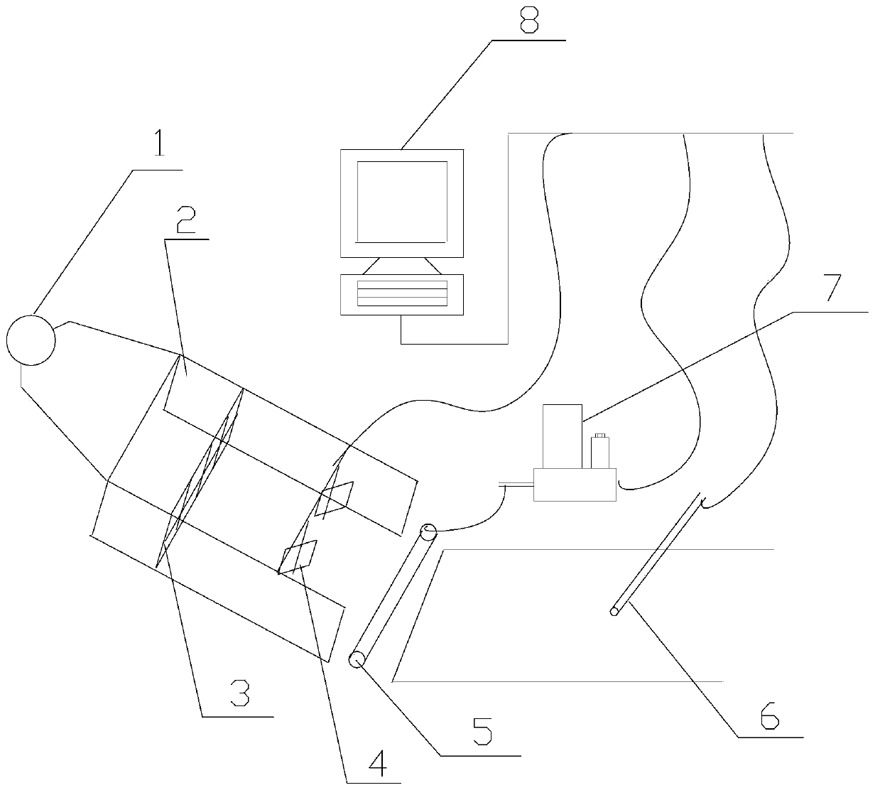
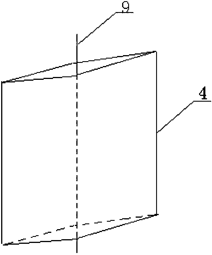
[0034] like figure 1 As shown, a device for simultaneously controlling flame shape and flame temperature in this embodiment includes an air blower 1, an air duct 2, a steady flow grid 3, a guide vane 4, a burner 5, a thermocouple 6, and a gas mass flowmeter. 7, computer 8, test bench, etc. Each of the above devices is arranged in a combustion chamber, the combustion chamber is made of heat insulating material, and cameras are provided at several positions of the combustion chamber for observing the shape of the flame. The combustion plate to be tested is fixed on the test bench, the burner 5 is arranged between the air outlet of the air duct 2 and the test bench, and the air blower 1 supplies air through the air duct 2 .

[0035]In order to fully consider the influence of the external wind speed on the fire source flame, the fan 1 used in this embodiment is either a centrifugal fan or an axial flow fan, and the wind speed ranges from 0 to 10 m / s. Described combustion plate i...

Embodiment 2

[0048] The structure of this embodiment is the same as that of Embodiment 1 except for the following features:

[0049] In this example, the number of guide vanes 4 is 8, and the grid size is 80mm×80mm.

Embodiment 3

[0051] The structure of this embodiment is the same as that of Embodiment 1 except for the following features:

[0052] In this example, the number of guide vanes 4 is 10, and the grid size is 30mm×30mm.


PUM


Abstract

The invention discloses a device and a method for simultaneously controlling a flame shape and flame temperature. The device comprises an air supply fan, an air duct, a combustor, a mass flow meter, a temperature sensor, a controller and a test bench, wherein a plurality of flow deflectors are arranged in the air duct; and a rotating angle of each flow deflector can be adjusted. The method comprises control over air speed, the flame shape and the flame temperature, and specifically comprises the following steps of roughly adjusting the air speed by using a fan frequency modulator, and finely adjusting the air speed at an outlet by using the flow deflectors; controlling the air speed at each point on a combustion board to realize different shapes of flame; and transmitting temperature data to the controller by using the temperature sensor, thereby regulating a set fuel gas flow value or a fuel gas type to realize control over the flame temperature. According to the device and the method, the fan is used for simulating external air when a fire outside a building happens, an automatic control device is used for controlling the flow deflectors to remotely and accurately control the air speed, and the mass flow meter is used for controlling fuel gas flow to control the flame temperature.

Description

technical field [0001] The invention relates to the field of simulated fire source control, in particular to a device and method for simultaneously controlling flame shape and flame temperature. Background technique [0002] With the frequent occurrence of fires nowadays, how to reduce the occurrence of fires has always been a difficult problem in front of people. Starting from the material itself, improving the fire safety performance of the material is one of the effective methods to reduce the occurrence of fire. How to evaluate the fire safety performance of materials and provide the basis for users to choose and judge is a very important work. For the evaluation of the fire performance of building decoration materials, roofing materials, solar photovoltaic products and modules, the commonly used method is to simulate a possible fire source to ignite or fire the tested sample, and observe whether it spreads, expands, etc. This method requires that the simulated fire so...

Claims


Application Information

Patent Timeline
Patent Type & Authority Applications(China)
IPC IPC(8): F23N5/00
Inventor 易爱华杨展林玩君刘建勇赵侠凌翩余稳松吴欣邬玉龙李海伦
Owner 广州市建筑材料工业研究所有限公司
Why Eureka
Eureka Blog
Learn More