Device and method for separating iron shapes from castings in shells of wheel reducers

A wheel reducer and iron mold technology, which is applied to the device for separating the iron mold from the casting in the wheel reducer housing, the separation of the iron mold and the casting in the iron mold sand-covered casting wheel reducer housing, the device field, can Solve the problems that the iron mold and the casting in the wheel reducer shell cannot be separated, the casting is damaged, the vibrator is damaged, etc., and the cleaning process of the iron mold is simplified, the production process is shortened, and the damage is small.

Active Publication Date: 2013-11-20
浙江省机电设计研究院有限公司
View PDF7 Cites 8 Cited by
  • Summary
  • Abstract
  • Description
  • Claims
  • Application Information

AI Technical Summary

Problems solved by technology

This patent is very convenient to separate the iron mold and castings of wheel castings to meet the mass production of wheel castings. However, if the wheel side reducer housing adopts the above patent, there are the following defects: because the wheel side reducer housing castings have relatively Large flange, side vibrator collides with the flange of the wheel side device shell casting, it is easy to damage the vibrator; two pieces are used in one box, if the side vibrator is used, two vibrators are required to vibrate at the same time Hit the two castings to maintain the uniformity and consistency of the vibration, otherwise the uneven vibration will easily jam the casting; the side vibrating device directly hits the casting, and when the shock force is too large, it is easy to cause cracks in the casting; the ejector rod directly Under the action of the casting, the damage to the casting is large, and a large ejection force is required to separate the casting from the iron mold
The patent includes a gantry-type bracket, the top of the bracket is fixed with a cylinder, and the lower part of the bracket is equipped with a horizontal impact plate, the mold moves to the casting demoulding station, and the clamping movable frame moves downward under the push of the cylinder. , the pouring riser was impacted, and the casting loosened and fell off from the upper mold. Although the problem of high labor intensity of the operator was solved, when the casting of the reducer housing was produced, after the casting was poured, as the casting was completely solidified, further During the cooling process of the casting, the casting is gradually shrinking due to the cooling. When the casting reaches the unpacking temperature for unpacking, the casting has been completely and tightly wrapped on the self-contained core of the lower iron type, and the wrapping force is very large, which only depends on the cylinder The jacking force will completely push the casting away from the upper iron mold, which requires a lot of jacking force. If a larger jacking force is used to lift the sprue in the gating system, it is likely that the connection between the gating system and the casting in the gating system will be damaged. Deformation occurs due to excessive force, and in severe cases, the connection between the gating system and the casting may even be broken, the casting is separated from the gating system, and the casting is still wrapped on the iron mold without being separated from the iron mold. The method of casting out of the box cannot realize the separation of the iron mold and the casting in the wheel reducer housing

Method used


Image

  • Device and method for separating iron shapes from castings in shells of wheel reducers
  • Device and method for separating iron shapes from castings in shells of wheel reducers
  • Device and method for separating iron shapes from castings in shells of wheel reducers

Examples


Embodiment Construction

[0026] The present invention will be further described below in conjunction with the accompanying drawings and embodiments.

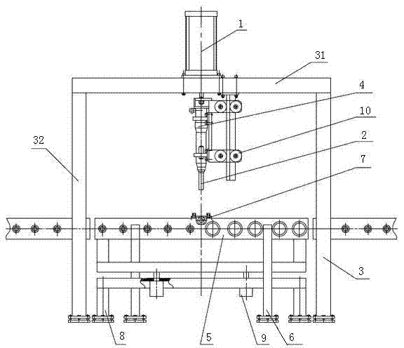
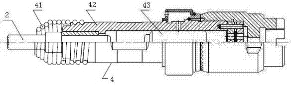
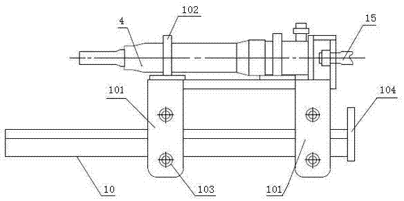
[0027] see Figure 1 ~ Figure 3 , this embodiment mainly includes ejection cylinder 1, ejector rod 2, frame 3, vibration device 4, iron-shaped conveying roller table 5, iron-shaped supporting pillar 6, iron-shaped positioning device 7, roller table receiving seat 8, roller table Lifting cylinder 9, ejector rod guiding mechanism 10, sand covering layer 11, sprue 12, iron mold 13, casting 14 and cylinder piston rod 15.

[0028] The roller table receiving seat 8 is directly installed on the ground below the frame 3, and the ejection cylinder 1 is fixedly installed on the upper plane of the upper beam 31 of the frame 3 with bolts. The frame 3, the roller table receiving seat 8 and the ejection cylinder 1 The center position coincides with the center point position of the whole device. The vibrating device 4 is located below the upper beam 31 of the frame 3...


PUM


Abstract

The invention relates to a device and a method for separating iron shapes from castings in shells of wheel reducers, and belongs to the field of sand-lined casting for iron shapes. The device comprises a framework, an ejection cylinder, a vibration device, an iron shape conveying roll table, iron shape carrying struts, roll table lifting cylinders and ejector rob guiding mechanisms. The iron shape carrying struts are connected with the iron shape conveying roll table, the roll table lifting cylinders are fixed onto roll table carrying seats, one end of each ejector rod guiding mechanism is connected with the framework, the other end of each ejector rod guiding mechanism is connected with the ejection cylinder, the ejector rod guiding mechanisms act along with vertical actions of the ejection cylinder, vibration force generated by the vibration device and ejection force generated by the ejection cylinder act on the same straight line, and the acting direction of the ejection force is consistent with that of the vibration force. The device and the method have the advantages that the castings in the shells of the wheel reducers can be conveniently separated from the iron shapes, the device is simple in structure and convenient to operate, and requirements of large-scale production can be met.

Description

technical field [0001] The present invention relates to a device and a method, in particular to a device and method for separating the iron mold and the casting in the shell of the wheel-side reducer, which is mainly used for the separation of the iron mold and the casting in the shell of the wheel-side reducer for iron mold sand-covered casting Separation belongs to the field of casting. Background technique [0002] The wheel reducer shell of the automobile is made of nodular cast iron, and its shape is a cylindrical casting. Sand-covered casting production is superior to ordinary sand casting in terms of economy, product quality and internal mechanical properties. [0003] The iron mold sand-covered casting of the wheel reducer shell casting of the automobile adopts the production method of one mold and two pieces. For mass production, the inner cavity of the casting is generally formed by the iron mold sand-coated self-made core, which will be formed soon. The shape of...

Claims


Application Information

Patent Timeline
Patent Type & Authority Applications(China)
IPC IPC(8): B22D29/06
Inventor 潘东杰黄列群沈永华应浩夏小江高强马益诚朱丹刘同帮汤瑶费巍峻
Owner 浙江省机电设计研究院有限公司
Why Eureka
Try Eureka