Efficient concrete stirrer

A mixer and concrete technology, which is applied to cement mixing devices, clay preparation devices, chemical instruments and methods, etc., can solve problems such as large operating vibration, achieve high mixing efficiency, reduce concrete shaft clumping, and improve mixing efficiency Effect

Active Publication Date: 2013-11-20
陈建凡
View PDF6 Cites 2 Cited by
  • Summary
  • Abstract
  • Description
  • Claims
  • Application Information

AI Technical Summary

Problems solved by technology

The agitator solves the problem of large running vibration caused by large eccentricity in the prior art, and runs smoothly, increases the flow speed of the material, stirs more vigorously, mixes more fully and more uniformly, and therefore has higher stirring efficiency

Method used


Image

  • Efficient concrete stirrer
  • Efficient concrete stirrer
  • Efficient concrete stirrer

Examples


Embodiment Construction

[0022] In order to make the technical problems, technical solutions and beneficial effects to be solved by the present invention clearer and clearer, the present invention will be further described in detail below in conjunction with the accompanying drawings and embodiments. It should be understood that the specific embodiments described here are only used to explain the present invention, not to limit the present invention.

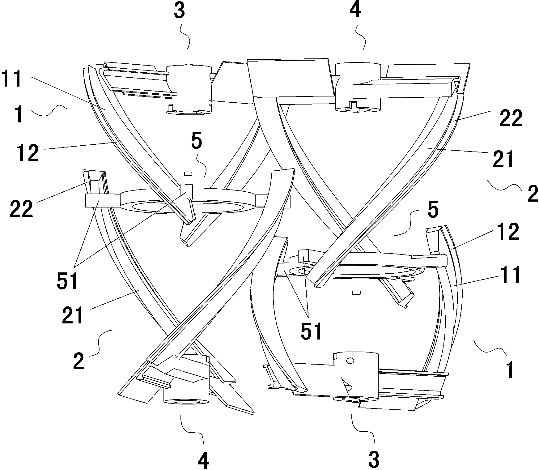
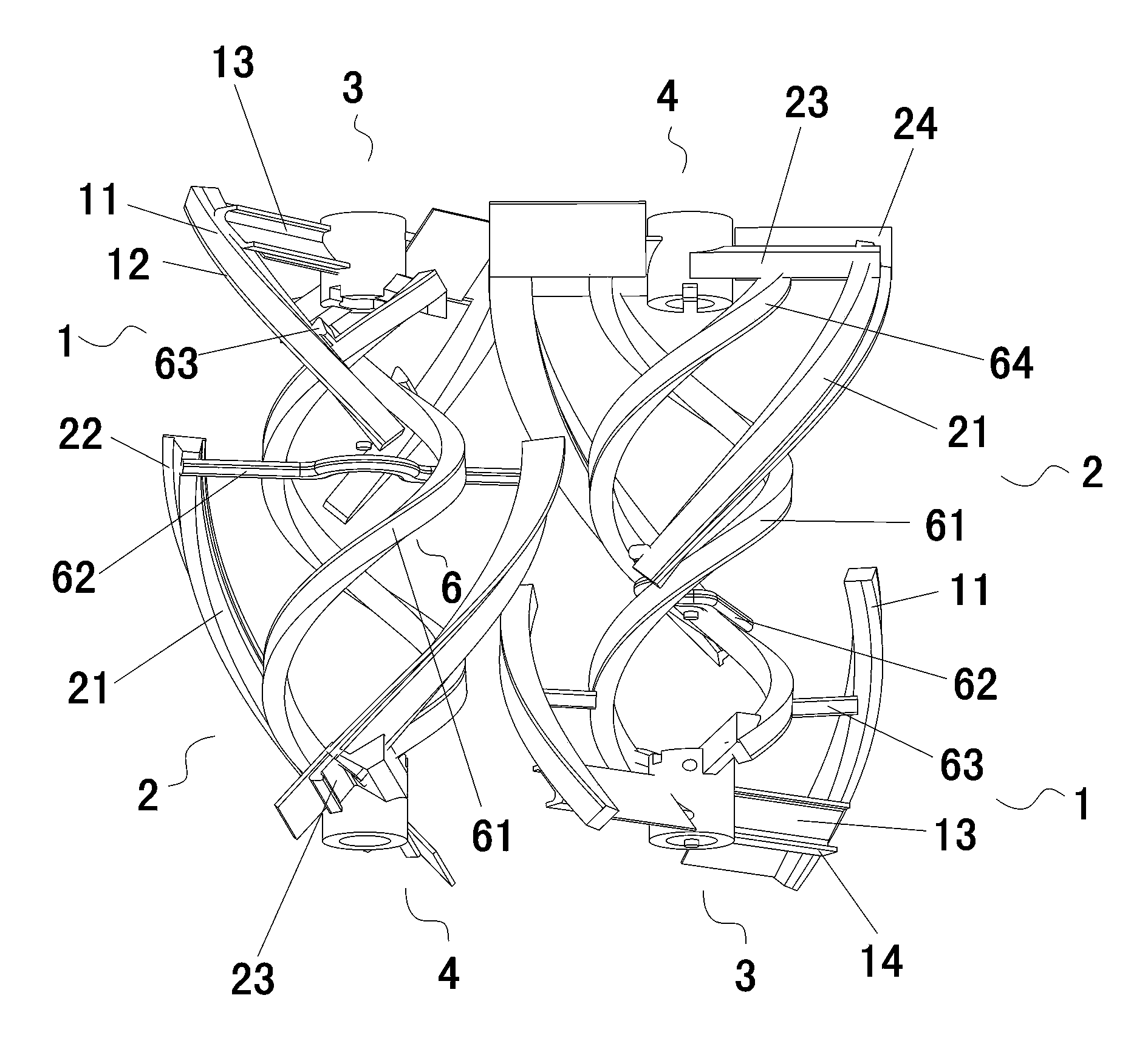
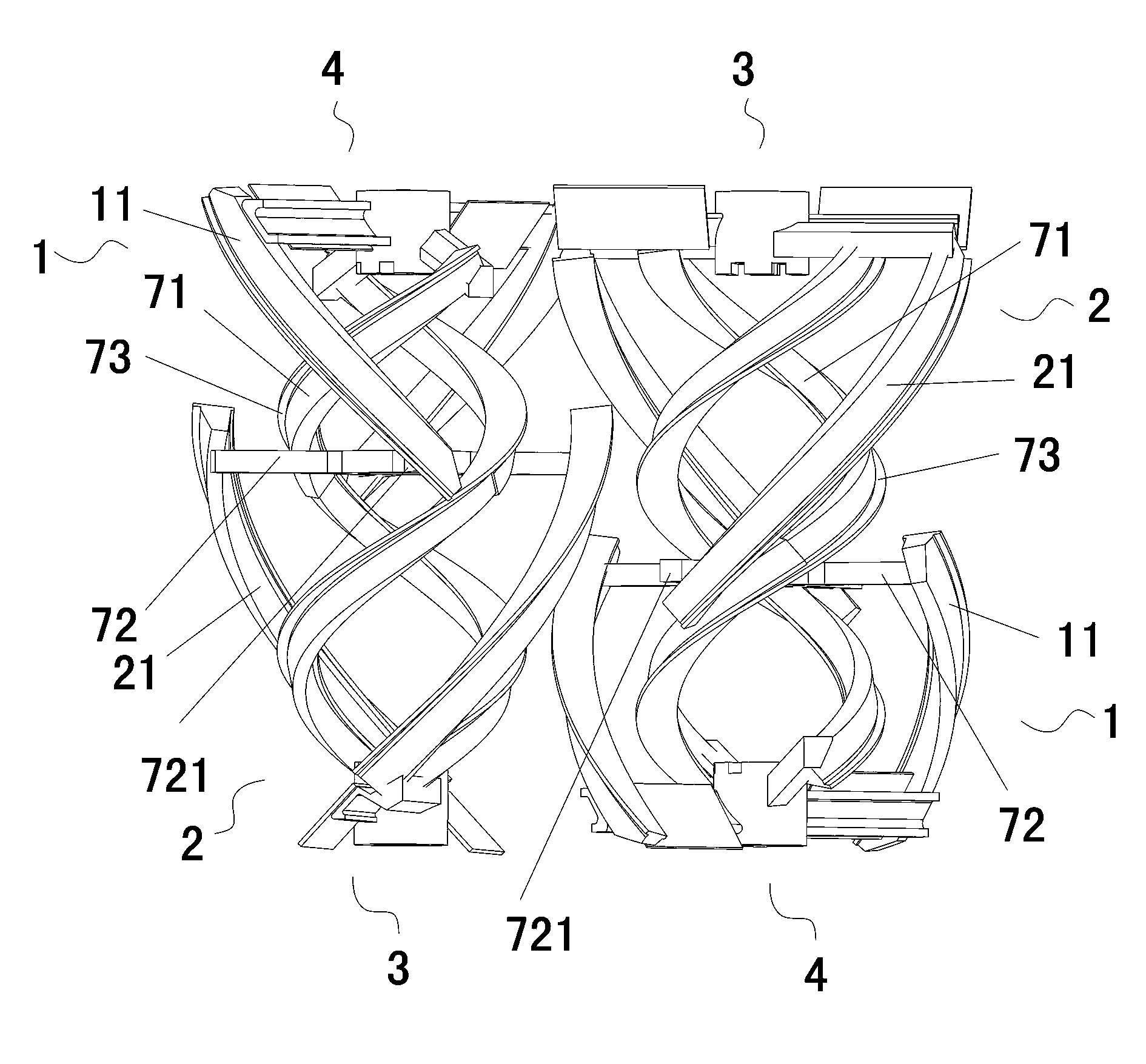
[0023] Such as figure 1 , 2 , A high-efficiency concrete mixer shown in 3, the mixer includes more than one group of mixing components, each group of mixing includes an outer screw feed shaft 1 and a screw return shaft 2. One end of the outer screw feed shaft 1 and the screw return shaft 2 are respectively connected to the driving end 3 and the driven end 4 of the motor, and the other ends are connected to each other through a shaft connecting piece.

[0024] Optimally, the agitator of the present invention comprises more than two groups of agitating ...


PUM


Abstract

A disclosed efficient concrete stirrer comprises more than one stirring assembly, and the installing directions and the rotating directions of the adjacent stirring assemblies are opposite. One end of an outer spiral feeding shaft and one end of a spiral returning shaft in each stirring assembly are respectively connected with the active end and the passive end of a motor, and the other ends are connected with each other via a connection piece. The connection piece is an annular piece, the ends of the outer spiral feeding shafts and the ends of the spiral returning shafts are uniformly distributed on and connected with the annular piece; or an inner spiral feeding shaft is additionally disposed for connection of the active end and the passive end of the motor; or on the basis of additional arrangement of the inner spiral feeding shaft, the annular piece is dismantled into a first connection piece and a second connection piece, wherein the first connection piece is connected with the inner spiral feeding shaft and the outer spiral feeding shaft, and the second connection piece is connected with the inner spiral feeding shaft and the spiral returning shaft. The stirrer of the invention helps to solve the problem in the prior art that operation vibration is large because of large eccentricity, and has stable operation, increased material flow speed, severer stirring, fuller and more uniform mixing, and higher stirring efficiency.

Description

technical field [0001] The invention relates to a spiral mixing device, in particular to a mixing mechanism of a mixer used for mixing concrete. Background technique [0002] The current concrete mixer generally adopts a mixing mechanism running around a horizontal axis, and the mixing device usually adopts a double helical crankshaft structure. Please refer to the Chinese patent document ZL201020614615.0 "a double-helix concrete mixer" published on June 1, 2011. The mixer only consists of a set of stirring devices installed in the mixing drum. Feed crankshaft and inner and outer two return crankshafts are composed, and also include connecting shafts connecting inner and outer feed crankshafts and inner and outer return crankshafts. The device adopts a split connection structure in which the inner feed crankshaft is connected to the outer return crankshaft, and the outer feed crankshaft is connected to the inner return crankshaft. Such a connection structure is easy to pro...

Claims


Application Information

Patent Timeline
Patent Type & Authority Applications(China)
IPC IPC(8): B28C5/10
Inventor 陈建凡
Owner 陈建凡
Why Eureka
Try Eureka