
Caterpillar track chassis of sandbeach cleaning trolley

A technology for a tracked chassis and a cleaning vehicle, which is applied to tracked vehicles, motor vehicles, vehicle parts, etc., can solve problems such as being unsuitable for large-scale beach cleaning operations, poor tire bearing capacity, and many working devices, to prevent sliding wear and improve driving. The effect of speed, good vibration reduction effect

Inactive Publication Date: 2013-11-20
XIAMEN UNIV OF TECH
View PDF5 Cites 4 Cited by
  • Summary
  • Abstract
  • Description
  • Claims
  • Application Information

AI Technical Summary

Problems solved by technology

[0002] The beach cleaning vehicle is mainly used to clean up the garbage on the coast beach. There are many working devices, complex structure, and the weight of the whole machine is relatively large.
At present, the walking mechanism of beach cleaning vehicles in the domestic and foreign markets is mainly tire-type. Due to the poor bearing capacity of the tires, it is prone to subsidence, especially when working on artificial beaches.
[0003] The existing crawler-type self-propelled beach cleaning vehicles generally have a fully rigid structure with rigidly fixed left and right crawler frames, small beach cleaning vehicles with a speed of less than 5km / h and a cleaning width of less than 1m, which are not suitable for cleaning large-scale beaches.

Method used


Image

  • Caterpillar track chassis of sandbeach cleaning trolley
  • Caterpillar track chassis of sandbeach cleaning trolley
  • Caterpillar track chassis of sandbeach cleaning trolley

Examples


Embodiment Construction

[0029] The present invention will be further described in detail below in conjunction with the accompanying drawings and specific embodiments.

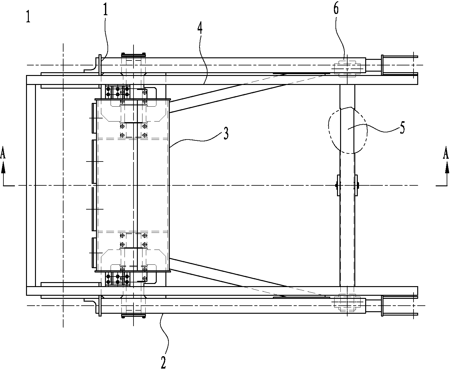
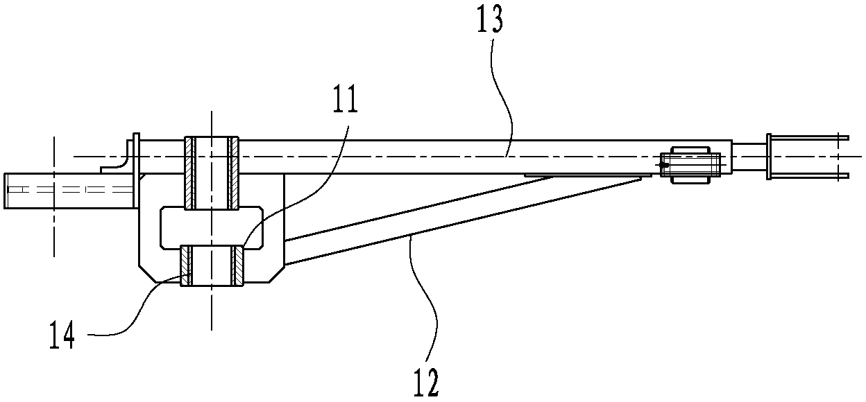
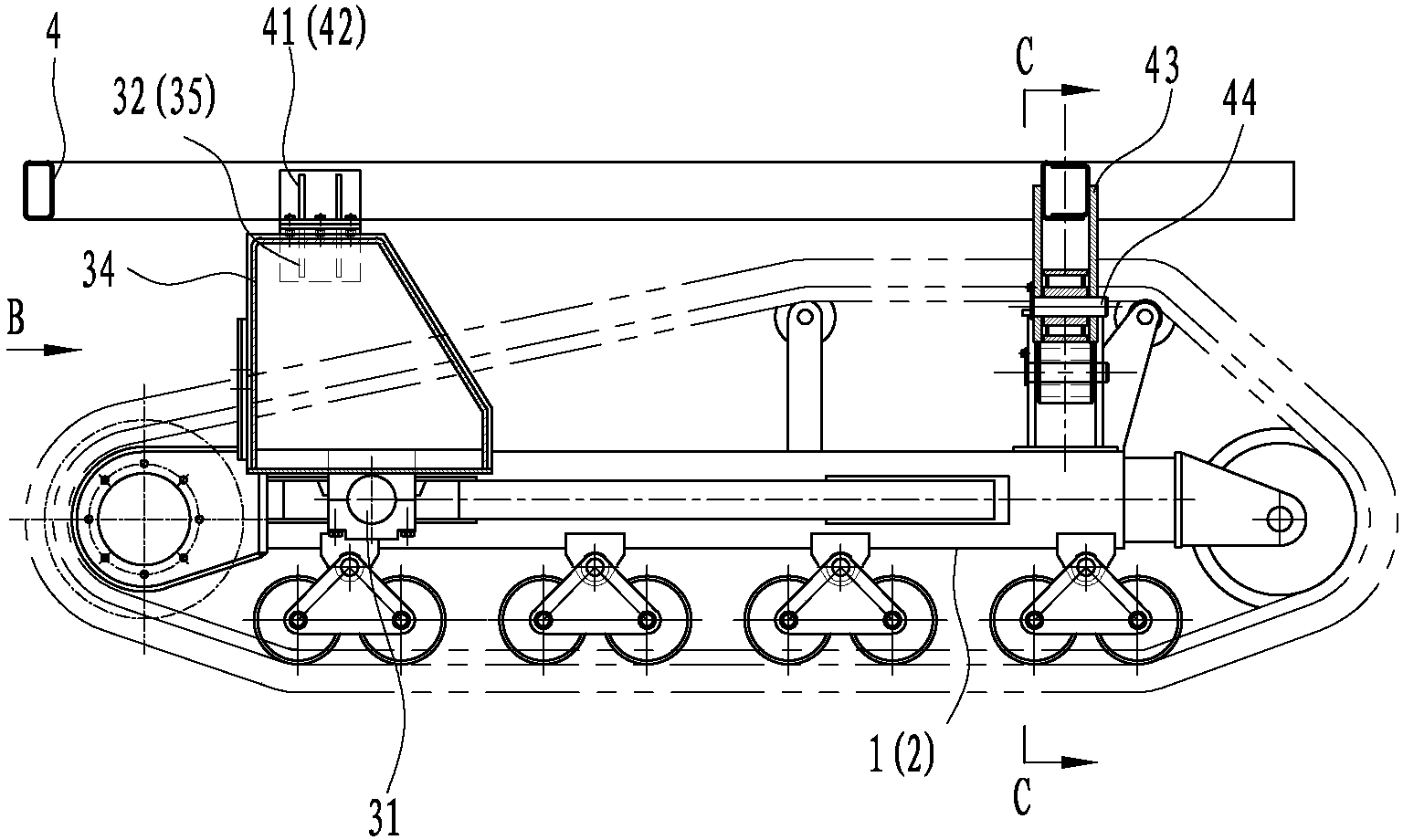
[0030] Disclosed by the present invention is a crawler chassis of a beach cleaning vehicle, such as Figure 1 to Figure 6 Shown is a preferred embodiment of the present invention. The crawler chassis includes a left crawler frame 1, a right crawler frame 2, a fuel tank 3, a vehicle frame 4, a balance beam 5 and a shock absorber 6. in:

[0031] The rear parts of the left and right crawler frames 1 and 2 are respectively hinged to the two ends of the fuel tank 3, and a shock absorber 6 is respectively provided at the front parts of the two, and the two ends of the balance beam 5 are respectively placed On the shock absorbers 6 on both sides, the front middle part of the vehicle frame 4 is connected to the middle part of the balance beam 5, and the rear two sides are connected to the two sides of the fuel tank 3, so that the vehicle fr...


PUM


Abstract

The invention discloses a caterpillar track chassis of a sandbeach cleaning trolley. The caterpillar track chassis of the sandbeach cleaning trolley comprises a left caterpillar track rack, a right caterpillar track rack, a fuel tank, a trolley frame, a balancing beam and dampers, wherein the rear portion of the left caterpillar track rack and the rear portion of the right caterpillar track rack are hinged to the two ends of the fuel tank respectively, the front portion of the left caterpillar track rack and the front portion of the right caterpillar track rack are respectively provided with one damper, and the two ends of the balancing beam are arranged on the dampers on the two sides respectively; the middle of the front of the trolley frame is connected to the middle of the balancing beam, the two sides of the rear of the trolley frame are connected to the two sides of the fuel tank, and therefore the trolley frame are respectively connected with the fuel tank and the balancing beam in a three-point connecting mode. Due to the fact that the rear portion of the left caterpillar track rack and the rear portion of the right caterpillar track rack can swing up and down along shafts on the two side of the fuel tank, the left caterpillar track rack and the right caterpillar track rack can achieve terrain-simulating driving, vibration of the trolley is reduced, and the driving speed is greatly improved; besides, due to the fact that the fuel tank is arranged below the trolley frame, the mass center height of the whole trolley is lowered, and loads of the trolley frame can be reduced.

Description

technical field [0001] The invention relates to the technical field of sanitation machinery, in particular to a crawler chassis for medium and large beach cleaning vehicles. Background technique [0002] The beach cleaning vehicle is mainly used to clean up the garbage on the beach. It has many working devices, complex structure and heavy weight. At present, the walking mechanism of beach cleaning vehicles in domestic and foreign markets is mainly tire-type. Due to the poor bearing capacity of tires, subsidence is prone to occur especially when operating on artificial beaches. [0003] The existing crawler-type self-propelled beach cleaning vehicles generally have a fully rigid structure with left and right crawler frames rigidly fixed. The small-sized beach cleaning vehicles with a speed of less than 5km / h and a cleaning width of less than 1m are not suitable for cleaning large-scale beaches. Therefore, medium and large crawler-type beach cleaning vehicles with a vehicle s...

Claims


Application Information

Patent Timeline
Patent Type & Authority Applications(China)
IPC IPC(8): B62D55/08B62D55/10B62D55/104B60K15/067
Inventor 欧阳联格黄红武葛晓宏周水庭谭璀璨叶玮嵘熊承杨
Owner XIAMEN UNIV OF TECH
Learn More