
Disc type drier

A drying machine and disc-type technology, applied in the direction of dehydration/drying/concentrated sludge treatment, etc., can solve the problem that the condensed water cannot be discharged quickly and in large quantities, increase the load of the central axis of the drying equipment, and reduce the service life of the drying equipment and other problems, to achieve the effect of not being prone to water hammer effect, prolonging the service life and reducing the risk of bending

Active Publication Date: 2015-06-24
天通新环境技术有限公司
View PDF6 Cites 2 Cited by
  • Summary
  • Abstract
  • Description
  • Claims
  • Application Information

AI Technical Summary

Problems solved by technology

[0004] The technical problem solved by the present invention is that in the prior art, the condensed water generated inside the intermediary object after heat exchange cannot be discharged quickly and in large quantities, resulting in a decrease in the heat exchange efficiency during the drying process of the material. And because the drying process of the drying equipment needs to be continuously rotated to ensure that the material is dried in place, when more and more condensed water cannot be discharged after heat exchange, the water hammer effect caused by the inertia will damage the drying equipment. At the same time, when the drying equipment stops running, the excessive water inside the intermediary object will increase the load of the shaft in the drying equipment, aggravate the bending of the shaft, and greatly endanger the safety of the equipment, reducing the service life of the drying equipment. And due to the increase of the overall quality of the equipment, the increase of drive power consumption and the waste of energy, a disc dryer with an optimized structure is provided.

Method used


Image

  • Disc type drier
  • Disc type drier
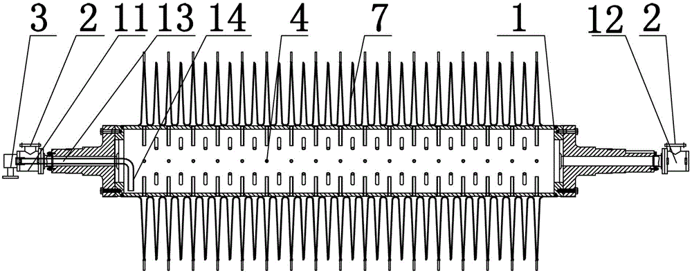
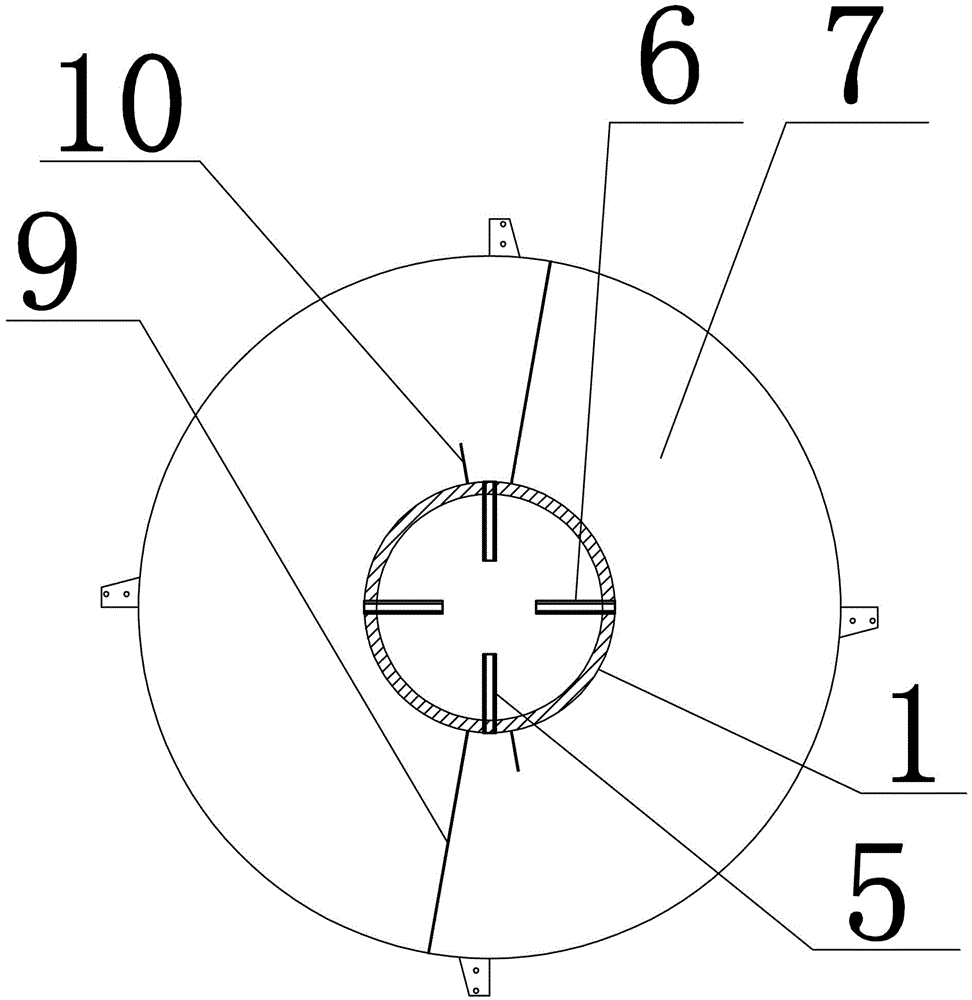
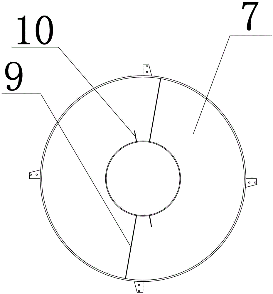
  • Disc type drier

Examples


Embodiment Construction

[0022] The present invention will be described in further detail below in conjunction with the examples, but the protection scope of the present invention is not limited thereto.

[0023] As shown in the figure, the present invention relates to a disc dryer, which includes a casing and a drying mechanism arranged in the casing. The drying mechanism includes a shaft 1 and shafts sleeved at both ends of the shaft 1. The shaft head is provided with a steam inlet 2 and a condensed water outlet 3; a number of guide tube groups 4 are evenly distributed on the shaft rod 1, and the guide tubes of each group of guide tube groups 4 are evenly distributed on the shaft On the same axial section of the rod 1, each set of guide tube groups 4 includes several condensate water guide tubes 5 and several steam guide tubes 6; There is a heat transfer plate 7, and the heat transfer plate 7 is welded by two disc-shaped sheets 8 facing each other; a number of deflector groups are arranged in the ra...


PUM


Abstract

The invention relates to a disc type drier. The disc type drier comprises a machine shell and a drying mechanism arranged in the machine shell, wherein the drying mechanism comprises a shaft rod and shaft heads sleeved at the two ends of the shaft rod, and the shaft heads are provided with steam inlets and condensate outlets; a plurality of guiding pipe groups are uniformly distributed on the shaft rod, guiding pipes of each guiding pipe group are uniformly distributed on the same shaft section of the shaft rod, and each guiding pipe group comprises a plurality of condensate water guiding pipes and a plurality of steam guiding pipes; heat transfer discs are sleeved on the shaft rod by corresponding to the guiding pipe groups one by one, and the heat transfer discs are formed by welding two disc-shaped pieces in an opposite manner; a radial gap formed by the two disc-shaped pieces is internally provided with a plurality of guiding plate groups, and the guiding plate groups are arranged in match with the condensate water guiding pipes. The disc type drier provided by the invention has the advantages that large amount of condensate water in the heat transfer discs can be rapidly discharged through the condensate water guiding pipes, and the heat exchange efficiency is high; the guiding pipe groups and the heat transfer discs are uniform to distribute and drain, a water hammer effect is unlikely to cause, the damage risk of the shaft rod is reduced, the service life of the drier is prolonged, the driving energy consumption is reduced, and the maintenance cost is reduced.

Description

technical field [0001] The invention belongs to the technical field of water, waste water, sewage or sludge treatment, and particularly relates to a method for quickly collecting and discharging the condensed water in the drying machine after the sludge is dried, so as to achieve higher heat exchange efficiency and facilitate the rapid drying of materials. It is a disc dryer that can dry and effectively prolong the service life of the dryer. Background technique [0002] Material drying refers to the process of removing most of the water content from the material by percolation or evaporation. In the material drying industry, the drying equipment can directly act on the material to make it dry, or use steam to dry indirectly. The steam does not directly contact the material, but indirectly dries the material through the heat conduction of the intermediary object. The latter It has the advantages of small exhaust gas volume and high drying efficiency. [0003] In the indire...

Claims


Application Information

Patent Timeline
Patent Type & Authority Patents(China)
IPC IPC(8): C02F11/12
Inventor 俞钱龙王志强陈建秀林毅许金发平志韩陈骝
Owner 天通新环境技术有限公司
Learn More