
Combined pressure quenching mandrel

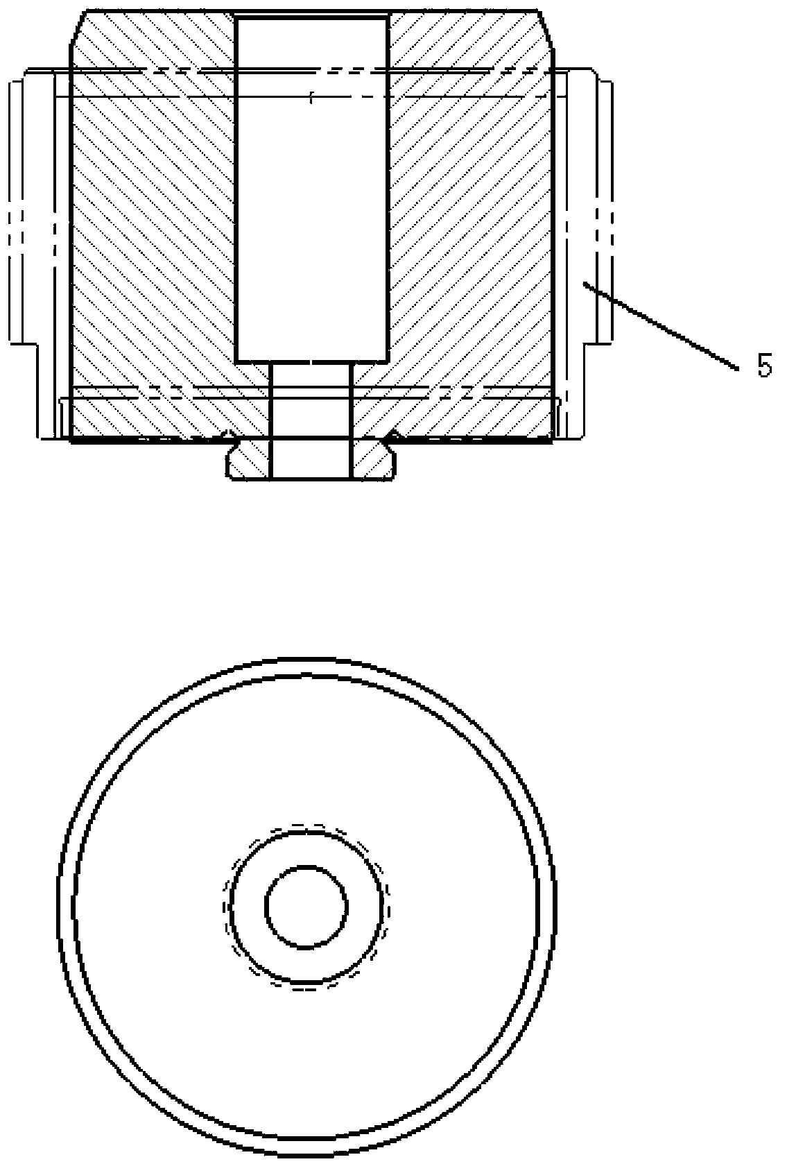
A combined, central axis technology, applied in the direction of quenching device, heat treatment equipment, manufacturing tools, etc., can solve the problems that the precision cannot meet the process requirements, the size difference between the upper and lower ends of the workpiece, and the roundness control of the workpiece is not very good. Reduced difficulty and improved workpiece accuracy

Active Publication Date: 2013-11-20
TIANJIN TIANHAI PRECISION FORGING
View PDF6 Cites 0 Cited by
  • Summary
  • Abstract
  • Description
  • Claims
  • Application Information

AI Technical Summary

Problems solved by technology

However, for gear sleeves with large size and thick structure, due to the large thickness of the workpiece, the difference in cooling consistency between the upper and lower end surfaces of the workpiece will also increase, and the roundness of the workpiece is often not well controlled. At the same time, the size of the upper and lower ends of the workpiece is also There is a big difference
The final precision of the workpiece cannot meet the process requirements

Method used


Image

  • Combined pressure quenching mandrel
  • Combined pressure quenching mandrel

Examples


Embodiment Construction

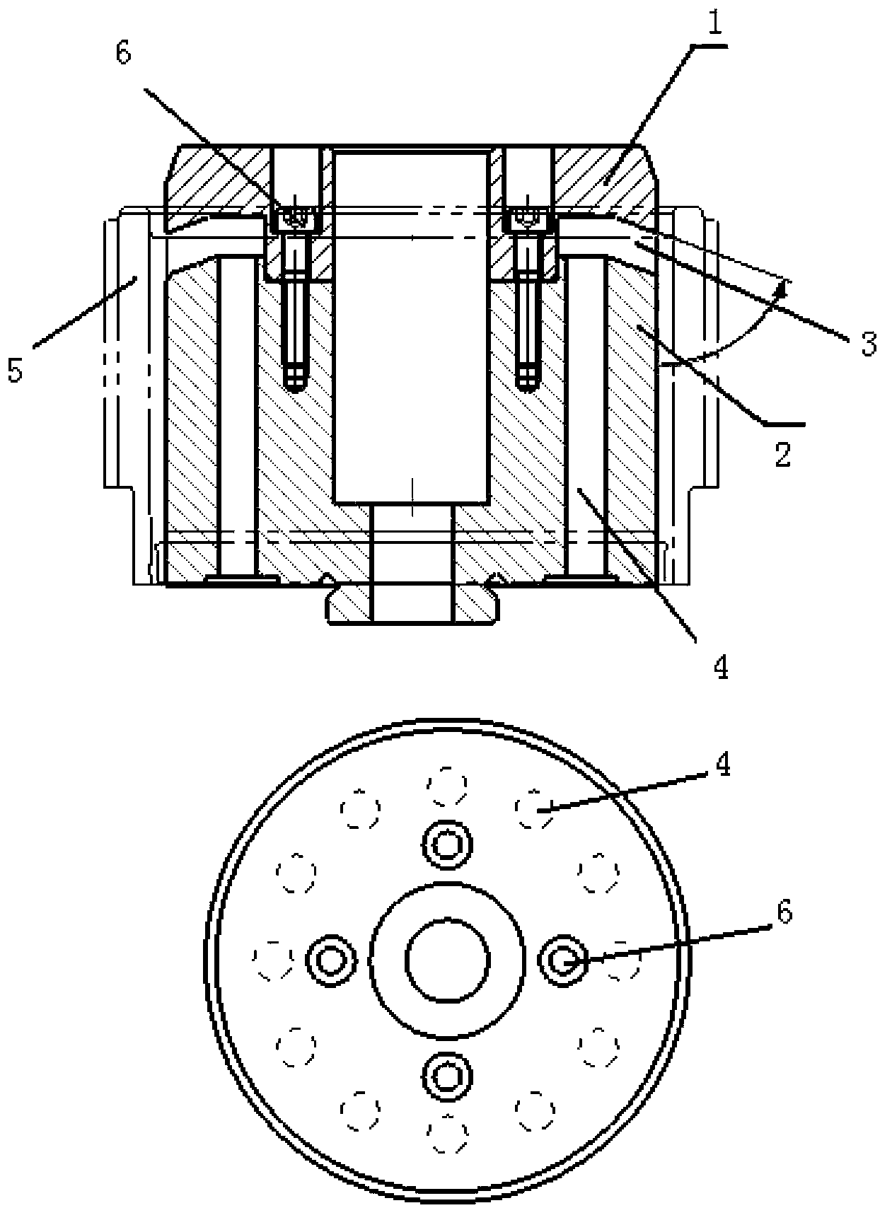
[0019] like figure 2 As shown, the present invention provides a combined press-quenching mandrel, the upper part 1 and the lower part 2 are fixed by the screw 6 penetrating through the convex part of the lower end of the upper part 1, the height of the top surface of the screw 6 is smaller than the height of the top surface of the upper part 1, The number of screws 6 is four. There is a gap between the upper part 1 and the lower part 2, which is the oil discharge oil passage 3, and there are 12 oil inlet oil passages 4 inside the lower part 2, and each oil inlet oil passage 4 communicates with the oil discharge oil passage 3 corresponding to its position , each oil inlet passage 4 is parallel to the central axis of the lower part 2 , and each oil inlet passage 4 is evenly distributed around the central axis of the lower part 2 . The acute angle formed between the outlet direction of the oil discharge oil channel 3 and the bus bar of the lower part 2 is 70°.

[0020] and fi...


PUM


Abstract

The invention provides a combined pressure quenching mandrel. The combined pressure quenching mandrel comprises an upper part and a lower part. The upper part is fixed above the lower part by a convex part at the lower end of the upper part so that gaps are formed between the upper part and the lower part, and the gaps are oil discharge passages. Multiple oil inlet passages are arranged in the lower part. The oil inlet passages are communicated respectively with the corresponding oil discharge passages. An angle between an outlet direction of the oil discharge passages and a lower generating line is an acute angle or an obtuse angle. Through the combined pressure quenching mandrel with the inclined cooling oil passages, a liquid coolant can flow along an inclined downward direction so that workpiece deformation control is promoted and a precision of a pressure-quenched workpiece is improved by 1 level. Through part respective-manufacture and assembling, manufacturing difficulty is greatly reduced.

Description

technical field [0001] The invention belongs to the field of metal heat treatment devices, and relates to a combined press-quenching mandrel. Background technique [0002] At present, for the shape-limited press quenching of synchronous devices, the mandrel with the small diameter of the embossed key is basically used as the form-limited press quenching. The shrinkage is guaranteed. However, for gear sleeves with large size and thick structure, due to the large thickness of the workpiece, the difference in cooling consistency between the upper and lower end surfaces of the workpiece will also increase, and the roundness of the workpiece is often not well controlled. At the same time, the size of the upper and lower ends of the workpiece is also There are large differences. The final precision of the workpiece cannot meet the process requirements. Contents of the invention [0003] The problem to be solved by the present invention is to provide a combined press quenching...

Claims


Application Information

Patent Timeline
IPC IPC(8): C21D1/673
Inventor 刘继武王永庆刘国才
Owner TIANJIN TIANHAI PRECISION FORGING
Learn More