Grooving perpendicularity control process of super-deep underground diaphragm wall

A verticality and trough-forming technology, which is applied to artificial islands, water conservancy projects, underwater structures, etc., can solve problems such as inability to carry out construction and difficulty in placing steel cages in place, and achieve the effect of shortening construction time

Active Publication Date: 2013-11-20
SHANGHAI YUANFANG GROUNDWORK ENG
View PDF7 Cites 4 Cited by
  • Summary
  • Abstract
  • Description
  • Claims
  • Application Information

AI Technical Summary

Problems solved by technology

In actual construction, these regulations are applicable to the underground diaphragm wall whose groove depth is not greater than 40m, but once the groove depth exceeds 40m, especially when the joints adopt rigid joints, it is difficult for the reinforcement cage to be lowered into place smoothly
However, for ultra-deep underground diaphragm walls with groove depth greater than 60m, construction cannot be carried out if the verticality of the groove is still controlled according to the existing regulations

Method used


Image

  • Grooving perpendicularity control process of super-deep underground diaphragm wall
  • Grooving perpendicularity control process of super-deep underground diaphragm wall

Examples


Embodiment Construction

[0014] The present invention will be further described below in conjunction with embodiment.

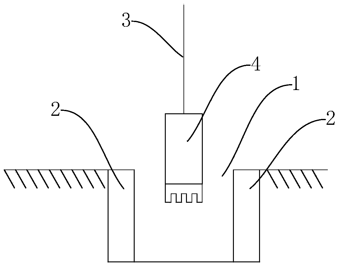
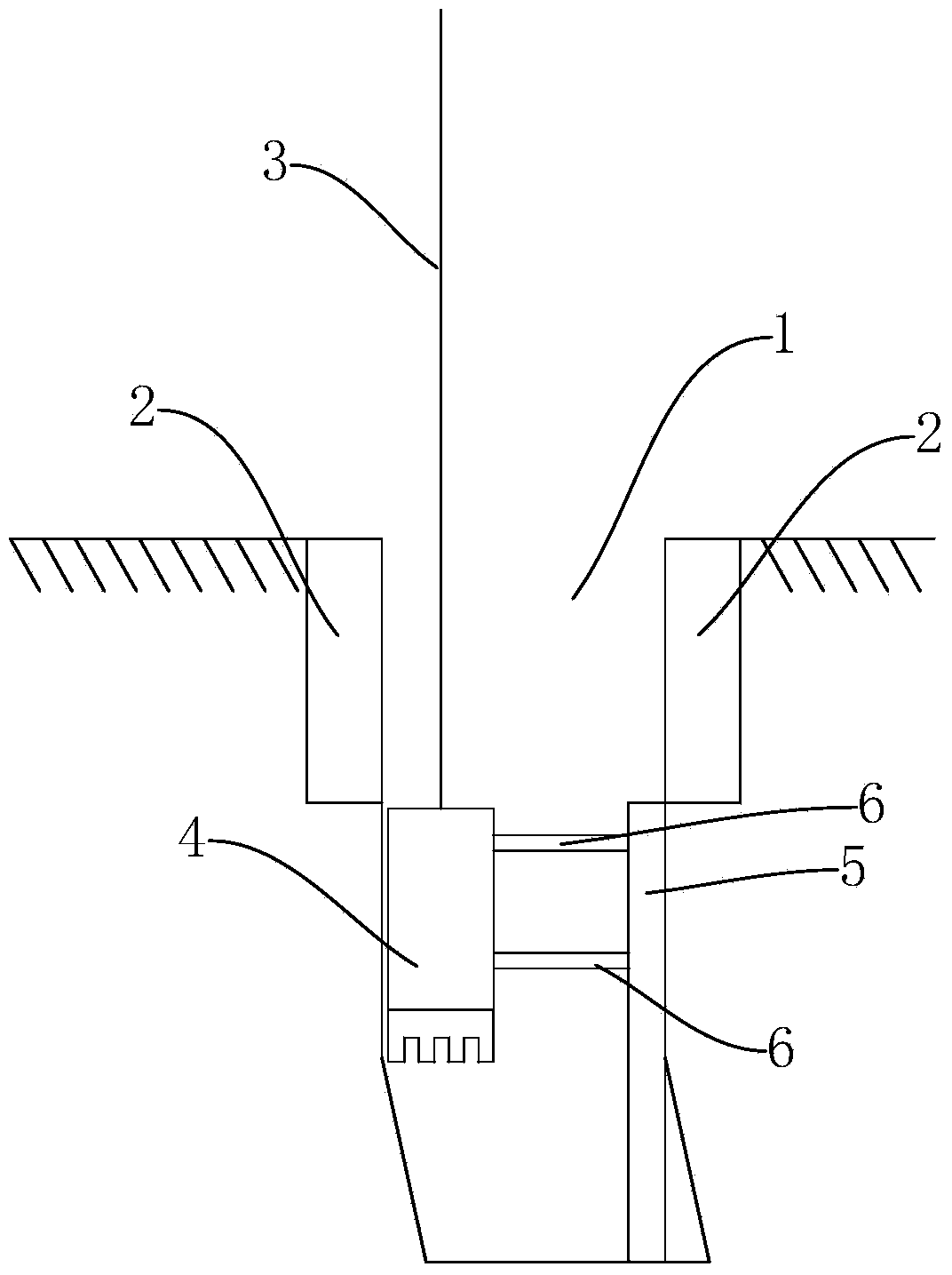
[0015] The ultra-deep underground diaphragm wall groove verticality control process uses hydraulic grabs to excavate to form grooves. Such as figure 1 As shown, before excavation, firstly, two sections of guide walls 2 are set according to the width of the slot 1 , and the distance between the two sections of guide walls 2 is the same as the width of the slot 1 . The guide wall 2 extends 1-1.5 meters deep from the ground to the ground. Utilize the wire rope 3 to hang the hydraulic grab bucket 4, so that the hydraulic grab bucket 4 is excavated between the two sections of guide walls 2. In the groove forming process, when the depth of the groove is less than 5-15 meters, the distance between the two sections of the guide wall 2 and the steel wire rope 3 is measured with a measuring stick. If the distance between the wire rope 3 and the two sections of the guide wall 2 is equal or t...


PUM


Abstract

The invention discloses a grooving perpendicularity control process of a super-deep underground diaphragm wall. A groove is formed by using a hydraulic grab through excavation, two sections of guide walls are arranged according to the width of the groove before excavation, the distance between the two sections of guide walls is equal to the width of the groove, the guide walls extend to underground for an appointed depth from the ground, the hydraulic grab is hung by using a steel rope to ensure that the hydraulic grab excavates between the two sections of guide walls. The grooving perpendicularity control process is characterized in that when the depth of the groove is less than 5-15m in a grooving process, the distances between the two sections of guide walls and the steel rope are measured by using a measuring ruler, the perpendicularity accords with the requirement if the distances between the steel rope and the two sections of guide walls are equal or the difference between the distances from the steel rope to the two sections of guide walls does not exceed 30cm, the excavation is carried out continuously; after the depth of the groove is more than 5-15m, when the excavation is carried out for a certain depth, the perpendicularity of the wall of the groove is measured by adopting an ultrasonic wall measuring apparatus, and the tunneling is carried out continuously if the perpendicularity of the side wall meets the requirement. The grooving perpendicularity control process of the super-deep underground diaphragm wall, disclosed by the invention, is capable of controlling the grooving perpendicularity of the underground diaphragm wall with a construction depth of exceeding 60m to be within 1/1000, and ensuring that an ultra-long reinforcement cage with I-beam joints at two ends is smoothly put in a design depth so that the construction time of the super-deep underground diaphragm wall is shortened.

Description

technical field [0001] The invention relates to a technique for controlling the verticality of grooves formed in an ultra-deep underground continuous wall. Background technique [0002] During the construction of the underground diaphragm wall, a groove is first excavated. When digging the trench, first extend from the ground to the ground to build two guide walls, the depth of which is generally 1-1.5 meters. A hydraulic grab is used to excavate a groove between the two sections of the guide wall, and the width of the groove is the same as the distance between the two sections of the guide wall. [0003] Excavation into the trench is usually done with a hydraulic grab. The hydraulic grab is suspended by a wire rope and is continuously excavated into a groove. Although the hydraulic grab is heavy, it can be kept vertical by its own weight when it hangs naturally. But when excavating, because after entering the soil layer, it will be subjected to the resistance and collis...

Claims


Application Information

Patent Timeline
Patent Type & Authority Applications(China)
IPC IPC(8): E02D29/02E02D33/00
Inventor 刘忠池姚海明陈兴华梁艳文姚健
Owner SHANGHAI YUANFANG GROUNDWORK ENG
Why Eureka
Try Eureka