Synchronous triggering management device and synchronous triggering management method

A technology for synchronizing triggering and managing devices, applied in instruments, computer control, simulators, etc., can solve problems such as inability to synchronize and trigger instruments, difficult management and unification of distributed test system triggering, and difficulty in building distributed test systems.

Inactive Publication Date: 2013-11-20
UNIV OF ELECTRONICS SCI & TECH OF CHINA
View PDF5 Cites 6 Cited by
  • Summary
  • Abstract
  • Description
  • Claims
  • Application Information

AI Technical Summary

Problems solved by technology

However, when forming a distributed test system, the trigger methods supported by each instrument are different, and each instrument does not have all the trigger methods, which leads to the inability of each instrument to directly synchro

Method used


Image

  • Synchronous triggering management device and synchronous triggering management method
  • Synchronous triggering management device and synchronous triggering management method
  • Synchronous triggering management device and synchronous triggering management method

Examples


Embodiment

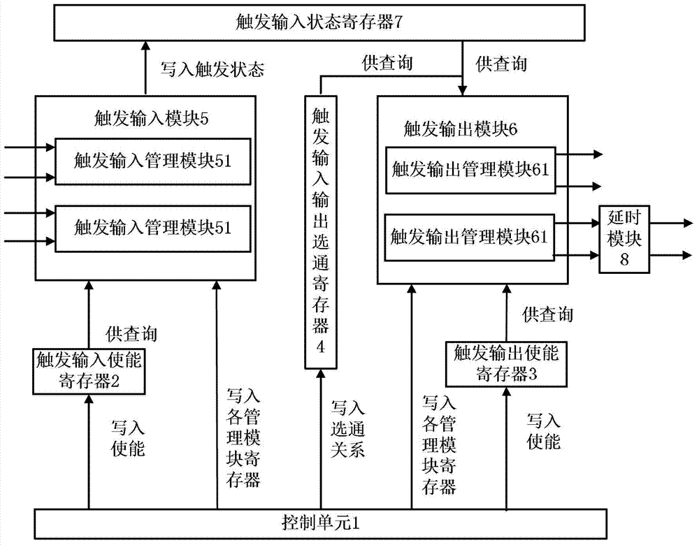
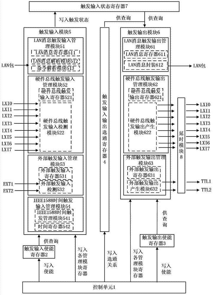
[0062] figure 2 It is a schematic structural diagram of an embodiment of a synchronization trigger management device in the present invention. Such as figure 2 As shown, the trigger input module 5 in this embodiment includes four common trigger input management modules in the prior art, which are respectively a LAN message trigger input management module 51, an 8-channel hardware bus trigger input management module 52, and a two-channel trigger input management module. An external trigger input management module 53 and an IEEE1588 time trigger input management module 54 . The trigger output module 6 includes three trigger output management modules, namely, a LAN message trigger output management module 61 , a hardware bus trigger output management module 62 , and an external trigger output management module 63 . The trigger input management module and the trigger output management module are not limited to those listed, and in implementation applications, one of the trigge...

application example 1

[0157] Figure 11 is a schematic diagram of Application Example 1 of the present invention. Such as Figure 11 As shown, the oscilloscope is an instrument that does not have a LAN port (network port) and cannot be connected to a local area network. It only has an external trigger input port EXT, and cannot directly control the trigger acquisition action of the oscilloscope through the local area network. The LAN port of the computer is directly connected to the LAN port of the synchronous trigger management device through a network cable, and the external trigger output port TTL1 of the synchronous trigger management device is directly connected to the external trigger input port EXT of the oscilloscope through a coaxial cable. Set the trigger input mode of the synchronous trigger management device to be LAN trigger, and the trigger output mode to be external trigger output, and the output is output by external trigger output port 1 (TTL1 port). At this time, the computer se...

application example 2

[0160] Figure 12 is a schematic diagram of application example 2 of the present invention. Such as Figure 12 As shown, the signal source has an external trigger function, but does not have the LXI hardware bus trigger function. Sources, computers, hubs, sync trigger managers, and LXI Class A oscilloscopes are Figure 12 Connected, the external trigger input port 1 (EXT1) of the synchronous trigger management device and the external trigger output port TTL of the signal source are connected through a coaxial cable, and the synchronous trigger management device and the hardware bus trigger interface LXI TRIG of the LXI Class A oscilloscope are connected through the LXI The trigger cable is connected, and the signal output port of the signal source is connected with the signal input channel 1 (CH1) of the LXI Class A oscilloscope through a coaxial cable. Set the trigger output mode of the synchronous trigger management device to hardware bus trigger output, the output channe...


PUM


Abstract

The invention discloses a synchronous trigger management device and a synchronous trigger management method. The method comprises the following steps of presetting a gating relation between a trigger input port and a trigger output port; when valid input of a trigger signal exists in an enabled trigger input port, enabling the status bit corresponding to the trigger input port in a trigger input status register to be 'valid input' by virtue of a trigger input module; obtaining the trigger input port gated with the enabled trigger output port according to the gating relation by virtue of a trigger output module; inquiring the status bit of the trigger input port in the trigger input status register; if the status bit is 'valid input', transmitting the trigger signal from the enabled trigger output port according to preset trigger output parameters by virtue of the trigger input module. The synchronous triggering management device is mainly applied to a distributed testing system, and can be used for conveniently realizing conversion between different trigger modes, enabling instruments with different trigger modes to trigger one another, and ensuring the sequential operation between a trigger signal generation instrument and a triggered instrument.

Description

technical field [0001] The invention belongs to the technical field of synchronous triggering, and more specifically, relates to a synchronous triggering management device and method. Background technique [0002] Synchronization and triggering is a key issue in distributed test systems. As the basis of the distributed test system, the networked instrument crosses the limitation of space, so that multiple instruments distributed in different geographical locations can work together to complete the test task. Compared with traditional instruments, networked test instruments support more trigger methods, currently including five trigger methods: driver-based command trigger, LAN (Local Area Network, local area network) message trigger, IEEE1588 (network measurement and control system Precision clock synchronization protocol standard) timing trigger, LXI (LAN-based eXtensions for Instrumentation, LAN-based instrument extension) hardware bus trigger and custom hardware trigger....

Claims


Application Information

Patent Timeline
IPC IPC(8): G05B19/042
Inventor 马敏戴志坚杨万渝
Owner UNIV OF ELECTRONICS SCI & TECH OF CHINA
Why Eureka
Try Eureka