
Display device

A display device and compensation unit technology, applied in static indicators, nonlinear optics, instruments, etc., can solve the problems of long wiring length, affecting product size, large size, etc., and achieve the effect of reducing occupied space and product size

Inactive Publication Date: 2013-11-20
BOE TECH GRP CO LTD +1
View PDF5 Cites 20 Cited by
  • Summary
  • Abstract
  • Description
  • Claims
  • Application Information

AI Technical Summary

Problems solved by technology

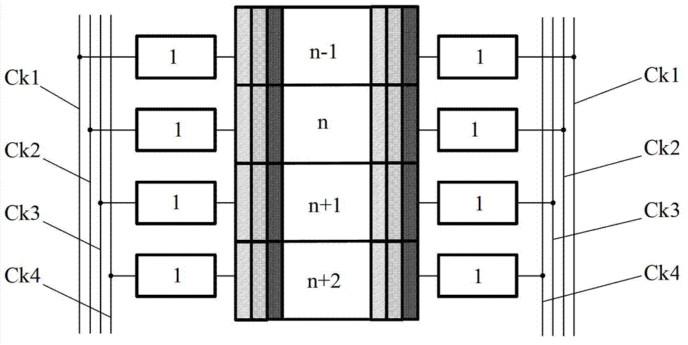
For large-scale displays (generally refers to displays larger than 19 inches), the structure of bilateral integrated gate drivers is usually adopted, that is, the gate drivers are integrated at both ends of the gate control line of the array substrate. Long length and high resolution, the large load (including large resistance and large parasitic capacitance) will delay the gate signal, and the delay of the gate signal will cause insufficient charging of the pixel and negatively affect the uniformity of the picture. Therefore, the large-scale panels in the prior art adopt the design of bilaterally integrated gate drivers, that is, the same gate drivers are integrated at both ends of the gate control line, such as figure 1 As shown, the gate driver includes a plurality of gate drive units 1, the input terminals of the gate drive unit 1 are respectively connected to the gate timing signal lines Ck1, Ck2, Ck3, Ck4, and the output terminals are respectively connected to the n-1th , n, n+1, and n+2 rows of gate control lines, which are used to drive gate control lines of n-1, n, n+1, and n+2 rows respectively
However, this design will cause the gate driver to take up a lot of space, so that the frame of the LCD panel needs more space, which affects the product size

Method used


Image

  • Display device
  • Display device
  • Display device

Examples


Embodiment Construction

[0021] The present invention will be described in detail below with reference to the drawings and embodiments.

[0022] It should be noted that in the description of the present invention, the orientation or positional relationship indicated by "up", "down", "left", "right", etc. is based on the orientation or positional relationship shown in the drawings, and is only for the convenience of describing the present invention. The simplified description of does not indicate or imply that the described device or element must have a specific orientation, and therefore cannot be understood as a limitation of the present invention.

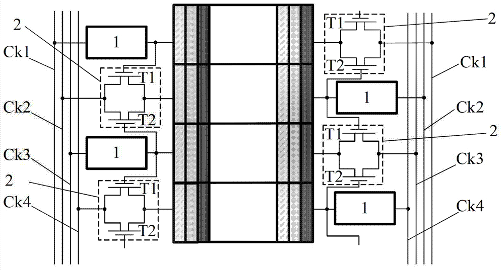
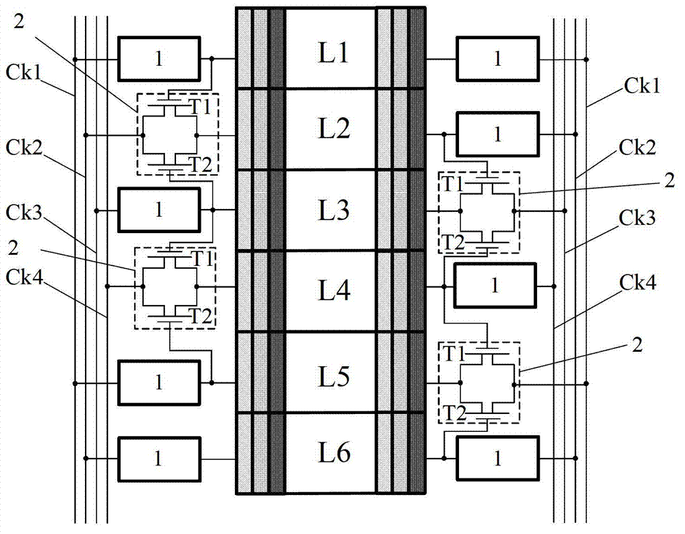
[0023] Such as figure 2 As shown, Ck1, Ck2, Ck3, and Ck4 are gate timing signal lines of the display device, and 1 is a gate driving unit. The display device proposed by the present invention includes a gate control line and a plurality of gate driving units 1, and also includes a plurality of compensation units 2. The compensation unit 2 is connected to the...


PUM


Abstract

The invention discloses a display device, which comprises a grid control line, a plurality of grid driving units, and a plurality of compensating units, wherein the compensating units are connected with the output ends of the two grid driving units and are connected with the grid control line. The display device has the advantage that the traditional double-edge dual grid driving unit structure is changed into a new structure of combining a double-edge single grid driving unit and a compensating structure, so the occupation space of a grid driver is reduced, and the size of the display device is reduced.

Description

Technical field [0001] The present invention relates to the field of display technology, and in particular to a display device. Background technique [0002] In the design of existing display devices such as liquid crystal displays, a gate driver is usually integrated on an array substrate. For small displays (generally a display smaller than or equal to 19 inches), a structure of a unilateral integrated gate driver is usually adopted, namely The gate driver is only integrated at one end of the gate control line of the array substrate. For large displays (generally referring to displays larger than 19 inches), the structure of dual-sided integrated gate drivers is usually adopted, that is, the gate drivers are integrated at both ends of the gate control line of the array substrate. The reason is that the large panel is large in size and the wiring Long length, high resolution, and the large load (including large resistance and large parasitic capacitance) that will cause the gat...

Claims


Application Information

Patent Timeline
IPC IPC(8): G09G3/36
CPCG09G2300/0408G09G2310/08G09G2310/0286G09G3/3677G09G2300/043G02F1/13306G02F1/136286G02F1/1368
Inventor 王峥
Owner BOE TECH GRP CO LTD
Learn More