Self-tightening sealing structure for single detector

A sealing structure and detector technology, which is applied in engine sealing, nuclear power generation, climate sustainability, etc., can solve problems such as gasket leakage, increased radiation dose, general sealing performance of sealing structures, etc., and achieve enhanced sealing effect , avoid leakage, improve the effect of sealing performance

Active Publication Date: 2013-11-20
NUCLEAR POWER INSTITUTE OF CHINA
View PDF7 Cites 10 Cited by
  • Summary
  • Abstract
  • Description
  • Claims
  • Application Information

AI Technical Summary

Problems solved by technology

Nowadays, for a single detector introduced into the stack, it is generally adopted to put the detector into a closed protective tube, and set a sealing structure for the protective tube. The sealing structure adopts a mandatory sealing method in which the thread provides a pre-tightening force to compress the gasket. This structure The disadvantage is that because the dete

Method used


Image

  • Self-tightening sealing structure for single detector
  • Self-tightening sealing structure for single detector
  • Self-tightening sealing structure for single detector

Examples


Embodiment 1

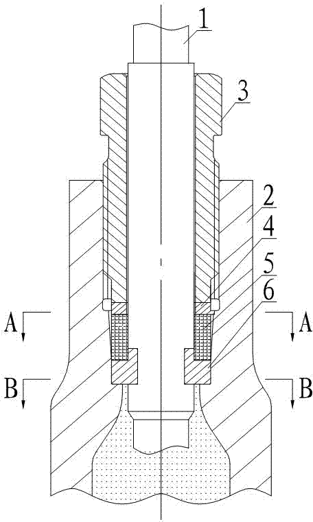
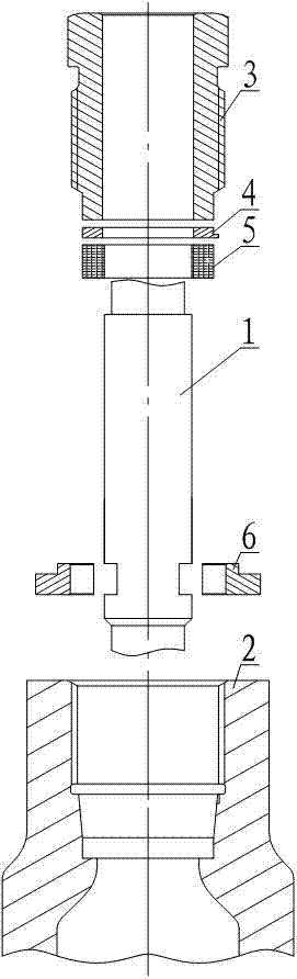
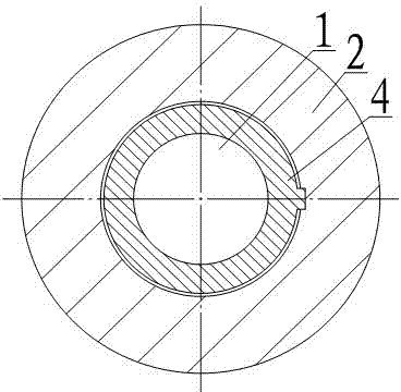
[0021] Such as figure 1 , figure 2 and Figure 4 As shown, a self-tightening sealing structure is used for a single detector, including a detector 1, a tube base 2 and a tubular connector 3. The tube base 2 is provided with a fluid cavity and a probe introduction channel, wherein the fluid cavity is in contact with the probe introduction channel. Normally, the fluid in the fluid cavity is usually coolant. The lower end of the tubular connector 3 is set in the detector introduction channel and connected to the tube base 2. The lower end of the detector 1 is arranged in the fluid chamber after passing through the inner hole of the tubular connector 3 and the detector introduction channel. The detector 1 is directly connected to the fluid chamber. The fluid contact inside can ensure the measurement response performance of the detector 1 when the detector 1 is used for measurement. The inner wall of the detector introduction channel forms an annular support platform, which can...

Embodiment 2

[0023] The main difference between this embodiment and Embodiment 1 is that this embodiment defines the following structure on the basis of Embodiment 1: the area where the packing seal 5 is accommodated in the detector introduction channel of this embodiment is large at the top and small at the bottom tapered inner hole. In this way, it can further ensure that the radial pressure distribution of the packing seal 5 is reasonable when it is compressed, which is more conducive to the self-tightening sealing of the packing seal 5 and reduces the pre-tightening force.

Embodiment 3

[0025] In this embodiment, on the basis of Embodiment 1 or Embodiment 2, the connection structure between the separation ring 6 and the detector 1 is further improved. In this embodiment, the connection between the detector 1 and the separation ring 6 forms a ring Groove, the separation ring 6 is connected with the detector 1 through its inner ring embedded in the annular groove.


PUM


Abstract

The invention discloses a self-tightening sealing structure for a single detector. The self-tightening sealing structure comprises the detector, a tube base and a tubular connecting piece, wherein the tube base is provided with a fluid cavity and a detector introducing passage communicated with the fluid cavity; the lower end of the tubular connecting piece is arranged inside the detector introducing passage and connected with the tube base; the lower end of the detector is arranged inside the fluid cavity after passing through an inner bore of the tubular connecting piece and the detector introducing passage. An annular supporting platform is formed on the inner wall of the detector introducing passage; the detector is connected with a separation ring which is positioned below the tubular connecting piece and arranged on the annular supporting platform; a filling sealing member is arranged in an area between the tubular connecting piece and the separation ring. The self-tightening sealing structure is simple integrally, is convenient to install and disassemble, and has a reliable self-tightening sealing function to ensure a good sealing effect and improve the safety of the detector.

Description

technical field [0001] The invention relates to a sealing structure for a detector in nuclear reactor core measurement, in particular to a self-tightening sealing structure for a single detector. Background technique [0002] Since the nuclear reactor core measurement system needs to measure the core outlet temperature, core neutron fluence rate or core water level, a variety of detectors are installed inside the reactor pressure vessel to measure the above parameters. The detectors are generally introduced into the stack in two ways, one is that multiple detectors are integrated into a bunch and introduced into the stack, and the other is that a single detector is introduced into the stack separately. [0003] When the detector is introduced into the stack, a sealing structure for the detector needs to be installed, and the sealing structure is installed on the pressure vessel socket to provide a sealing function for the detector. Nowadays, for a single detector introduced...

Claims


Application Information

Patent Timeline
IPC IPC(8): G21C17/10F16J15/06
CPCY02E30/30
Inventor 饶琦琦李娜何大明舒翔余志伟李燕陈训刚王留兵张翼周禹夏欣
Owner NUCLEAR POWER INSTITUTE OF CHINA
Why Eureka
Try Eureka