LED module and manufacturing method thereof

A technology of LED modules and manufacturing methods, which is applied in the direction of electrical components, electric solid devices, circuits, etc., can solve the problems of affecting the luminous performance of products, poor heat dissipation performance, and short service life, and achieve strong heat dissipation performance, long service life, The effect of small thermal resistance

Inactive Publication Date: 2013-11-20
深圳市天电光电科技有限公司
View PDF5 Cites 13 Cited by
  • Summary
  • Abstract
  • Description
  • Claims
  • Application Information

AI Technical Summary

Problems solved by technology

[0003] However, the current LED module structure has large thermal resistance and poor heat diss

Method used


Image

  • LED module and manufacturing method thereof

Examples


Embodiment approach

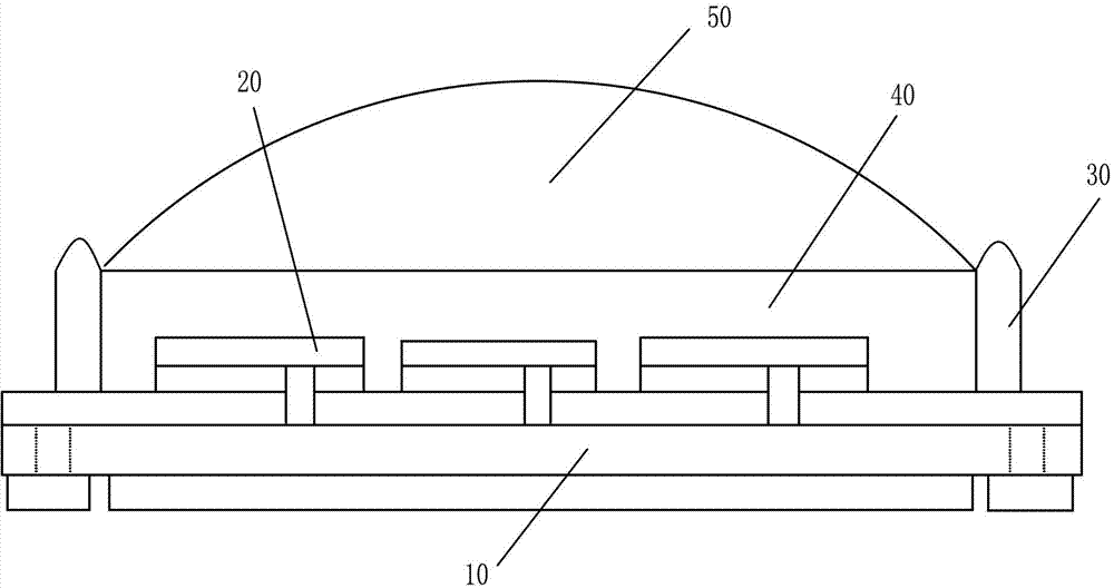
[0034] Flip-chip step: the LED chip 20 is flip-chip welded on the metal sheet of the high thermal conductivity ceramic substrate 10 by eutectic soldering, and a plurality of LED chips 20 are evenly arranged at predetermined intervals and predetermined orientations. Preferably, there are multiple LED chips, and a plurality of LED chips 20 are injected with dams 30 around the periphery. As an implementation, the flipping step also includes two sub-steps:

[0035] Soldering sub-step: coating flux on the surface of the metal sheet of the high thermal conductivity ceramic substrate 10, adhering the LED chip 20 to the metal sheet coated with flux; and

[0036] Soldering sub-step: reflow the high thermal conductivity ceramic substrate 10 adhered with the LED chip 20 through a reflow furnace at a predetermined temperature. Wherein, the predetermined temperature is 100°C to 360°C.

[0037] Injection step: injecting the dam 30 on the periphery of the LED chip;

[0038] Coating step: ...


PUM


Abstract

The embodiment of the invention discloses an LED module and a manufacturing method thereof. The LED module comprises high thermal conductivity ceramic substrate, an LED chip welded onto the substrate through eutectic bonding and flip chip bonding, a dam formed by performing injection molding on the periphery of the LED chip, a fluorescent glue layer formed by fluorescent glue arranged in the dam in a coating manner, and an optical structure layer covering the fluorescent glue layer. By adopting the technical means that the LED chip is welded on the high thermal conductivity ceramic substrate through eutectic bonding and flip chip bonding, the LED module achieves the technical effects of low thermal resistance, high heat dispersion, good luminescence property of products and long service life, has no gold thread, does not adopt solid crystal glue package, and has the characteristics of high brightness, high lighting effect, high reliability, low thermal resistance, good color uniformity and the like.

Description

technical field [0001] The invention relates to the technical field of LEDs, in particular to an LED module and a manufacturing method thereof. Background technique [0002] Light Emitting Diode (LED) is a solid-state semiconductor device that can convert electrical energy into light. It is widely used in display screens, traffic signals, display light sources, automotive lights, LED backlights, and lighting sources. . [0003] However, the current LED module structure has large thermal resistance and poor heat dissipation performance, which affects the luminous performance of the product and has a short service life. Contents of the invention [0004] The technical problem to be solved by the embodiments of the present invention is to provide an LED module with small thermal resistance and good heat dissipation performance. [0005] In order to solve the above-mentioned technical problems, an embodiment of the present invention proposes a method for manufacturing an LED...

Claims


Application Information

Patent Timeline
IPC IPC(8): H01L25/075H01L33/48H01L33/64
Inventor 周印华陈栋雷玉厚万喜红徐志坚吴叶青
Owner 深圳市天电光电科技有限公司
Why Eureka
Try Eureka