Load flow calculation method based on generator node type

A generator node and power flow calculation technology, applied in calculation, electrical components, circuit devices, etc., can solve problems such as difficult to reflect the relationship between generator voltage and reactive power

Inactive Publication Date: 2015-03-18
NORTHEAST DIANLI UNIVERSITY +1
View PDF3 Cites 0 Cited by
  • Summary
  • Abstract
  • Description
  • Claims
  • Application Information

AI Technical Summary

Problems solved by technology

The PV node model in the conventional power flow calculation is to set the generator voltage to a constant value, which is only an extreme operating condition of the generator, that is: β=0, so it is difficult to reflect the real voltage and reactive power relationship of the generator during the voltage regulation process

Method used


Image

  • Load flow calculation method based on generator node type
  • Load flow calculation method based on generator node type
  • Load flow calculation method based on generator node type

Examples


Embodiment Construction

[0041] The present invention will be further described below using the accompanying drawings and examples.

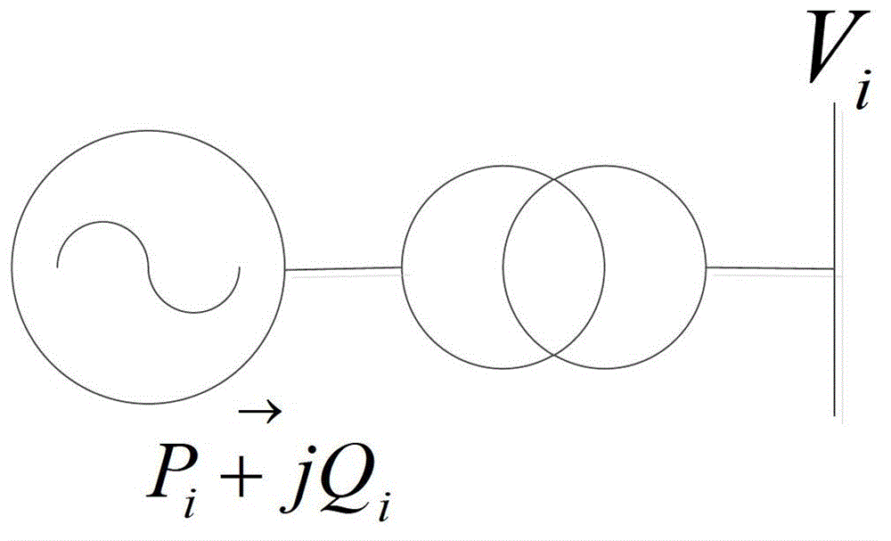
[0042] refer to figure 1 , a power flow calculation method based on generator node type of the present invention, it includes the following content:

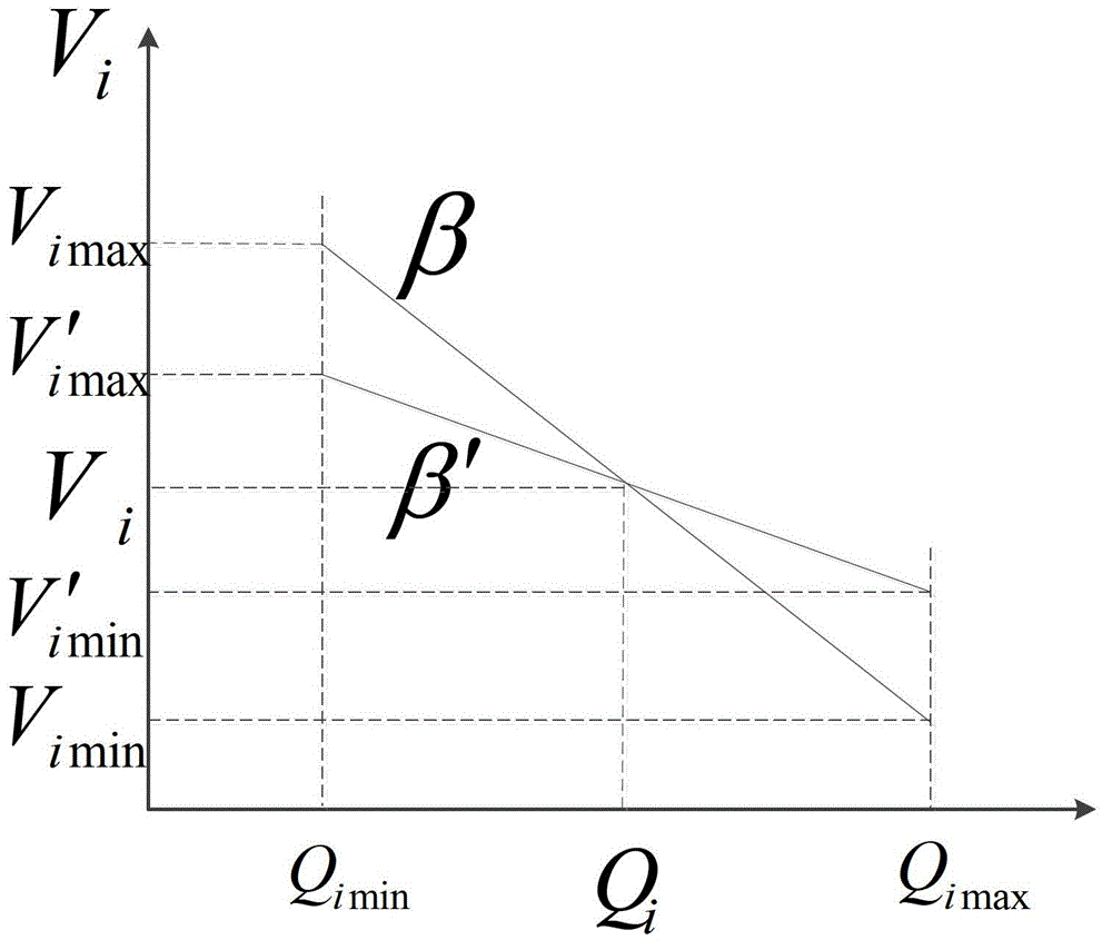
[0043] 1). Definition of Pβ node

[0044] Generator node is i, V i is the operating voltage of node i, P i Q i is the active power and reactive power of node i,

[0045] Then the adjustment coefficient of generator node i is:

[0046] β i = - V iref - V i Q iref - Q i = β i ( V i , ...


PUM


Abstract

The invention relates to a load flow calculation method based on a generator node type. The method is characterized in that a load flow calculation model containing a P beta node is generated by defining the P beta node, a new Jacobian matrix equation is established by adopting a Newton-Raphson method and finally the equation is modified to realize load flow iterative solution. By using the method, different voltage regulation requirements can be met by adjusting beta under the condition of given upper and lower limits of generator reactive power according to different positions of a generator in a system, the reactive regulation capacity of the generator can be fully utilized by correctly selecting beta, the situation that the generator loses the regulation capacity and becomes a PQ node due to a reason that reactive power exceeds the limits is avoided, and the actual voltage-reactive power relationship during the voltage regulation of the generator can be reflected.

Description

technical field [0001] The invention relates to the technical field of power flow calculation of generators, more specifically, a power flow calculation method of a generator node type taking into account the adjustment coefficient of an excitation system. Background technique [0002] The power flow calculation of the power system is the most basic calculation in the steady-state operation analysis of the power system. According to the known quantities of the nodes, the conventional power flow calculation sets the load node as the PQ node, the generator node as the PV node and the balance node Vθ. According to the defined node type, the power equation of each node is generated, and the unknown voltage and phase angle of each node are solved by iterative method. [0003] In fact, the voltage-reactive power relationship of the generator is determined by the adjustment coefficient β of its excitation system, that is, within the constraint range of the upper and lower limits of...

Claims


Application Information

Patent Timeline
Patent Type & Authority Patents(China)
IPC IPC(8): H02J3/00G06F19/00
Inventor 穆钢王明星马新安军刘伯林邵广惠徐兴伟侯凯元吴远志夏德明刘永奇王钢贾伟李泽宇张弘鹏岳涵王克非周莹
Owner NORTHEAST DIANLI UNIVERSITY
Why Eureka
Try Eureka