Lighting apparatus

A lighting equipment and irradiation technology, applied in lighting and heating equipment, lighting devices, components of lighting devices, etc., can solve problems such as engineering cost, reduce heat load, reduce thermal-related movement, and achieve luminous characteristics. Effect

Active Publication Date: 2013-11-20
CORETRONIC
View PDF11 Cites 6 Cited by
  • Summary
  • Abstract
  • Description
  • Claims
  • Application Information

AI Technical Summary

Problems solved by technology

This means high

Method used


Image

  • Lighting apparatus
  • Lighting apparatus
  • Lighting apparatus

Examples


Embodiment Construction

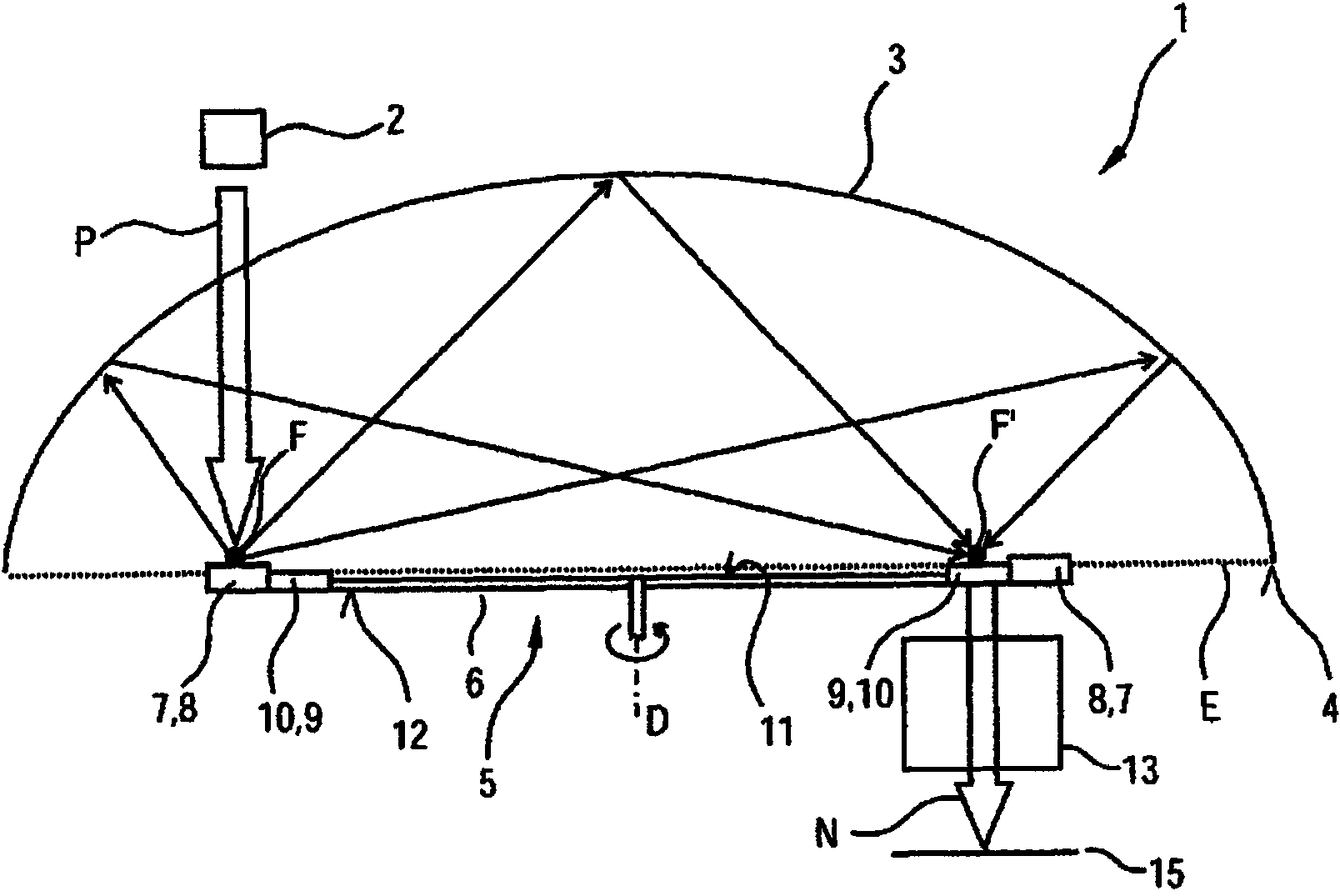
[0062] figure 1 A sectional side view of a lighting device 1 according to a first embodiment is shown. The lighting device 1 has a first light source in the form of a laser 2 which emits light in the form of (first) primary light P. The laser 2 can be, for example, a “blue laser” which emits blue light as primary light P or a “UV laser” which emits UV light as primary light P.

[0063] The lighting device 1 also has, as reflector means, an ellipsoidally shaped reflector 3 having a first focus F and a second focus F'. The focal points F, F' are here situated on or near the light exit plane E which is spread by the free edge 4 of the reflector.

[0064] The dome of the reflector 3 has a light-emitting wheel 5 of disc-shaped basic shape, which can be rotated about its axis of rotation D, for example by means of a drive motor (not shown). The reflector 3 has a sufficiently high eccentricity for this.

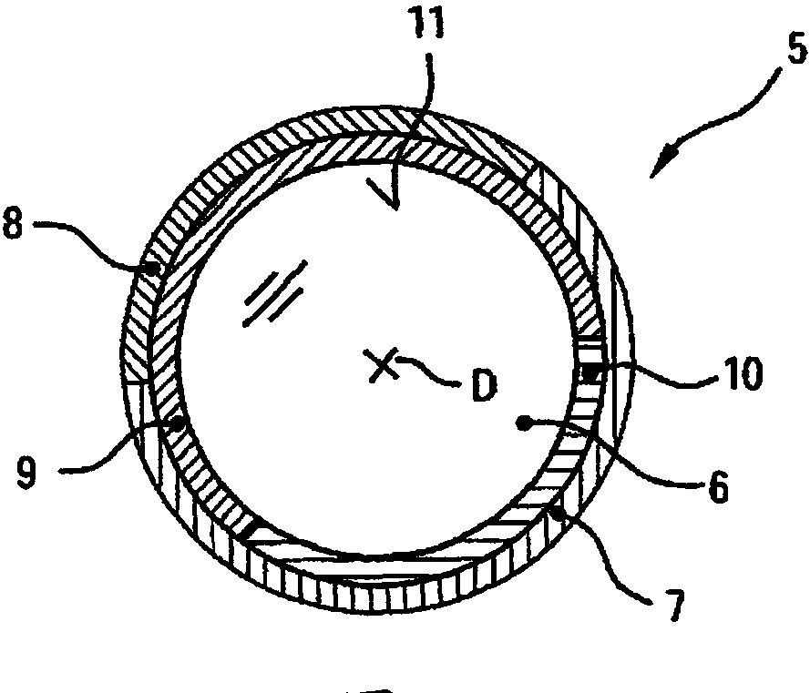
[0065] luminous wheel 5 in figure 2 is shown in the top view in . T...


PUM


Abstract

Lighting apparatus comprising a light source emitting primary light; a reflector device with first and second focal points; a rotatable light wheel with two functional regions; a primary light device irradiated by the light source and having functionally assigned to it one of the functional regions as a primary light functional region, the first focal point being located at the primary light device; a utility light device to which is functionally assigned another of the functional regions as a utility light functional region, the second focal point being located at the utility light device; a primary light functional region having in a first rotational position of the light wheel at least one phosphor sensitive to the primary light; and a utility light functional region being transmissive to the light whose wavelength is converted by the primary light functional region.

Description

technical field [0001] The invention relates to a lighting device having at least one first light source for emitting primary light, a reflector arrangement having a first focal point and a second focal point, at least one reflector device rotatable about an axis of rotation having at least two A luminous wheel of functional areas, one of which can be irradiated by means of at least one light source, wherein in a predetermined rotational position of the luminous wheel, the functional area which can be irradiated by means of the at least one light source has a response to the light emitted by the light source The primary light-sensitive, wavelength-converting at least one luminescent material. Background technique [0002] In projection applications based on the principally known LARP ("Laser Activate Remote Phosphor") technology, the luminescent material is irradiated by a laser and the incident light is partially converted by means of the luminescent material into a wavelen...

Claims


Application Information

Patent Timeline
IPC IPC(8): G02B7/00F21V9/40
CPCF21V13/08G03B21/204F21Y2101/025F21V7/08F21V9/10H04N9/3114F21V17/02F21V9/16F21K9/56F21Y2101/02F21V13/14G02B7/006F21K9/64F21Y2115/10F21Y2115/30F21V9/35F21V9/45H01S5/0087
Inventor 克劳斯·芬斯特布施乌尔里希·哈特维希
Owner CORETRONIC
Why Eureka
Try Eureka