Backfill type friction stir welding method and device

A technology of friction stir and welding method, which is applied in the direction of welding equipment, non-electric welding equipment, metal processing equipment, etc., and can solve the problem that the keyhole after welding cannot be eliminated

Inactive Publication Date: 2013-11-27
BEIJING AERONAUTICAL MFG TECH RES INST
View PDF8 Cites 42 Cited by
  • Summary
  • Abstract
  • Description
  • Claims
  • Application Information

AI Technical Summary

Problems solved by technology

However, when the weld seam is an intermittent weld seam and requires a uniform penetration depth, the keyhole after welding cannot be eliminated by using a retraction device.

Method used


Image

  • Backfill type friction stir welding method and device
  • Backfill type friction stir welding method and device
  • Backfill type friction stir welding method and device

Examples


Embodiment Construction

[0023] The technical scheme of the present invention will be described in further detail below in conjunction with accompanying drawing and embodiment:

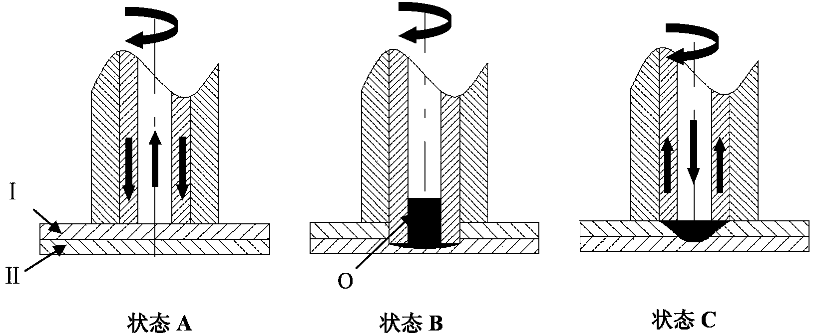
[0024] See attached Figure 3-4 As shown, this kind of backfilling friction stir welding method is characterized in that: the steps of the method are:

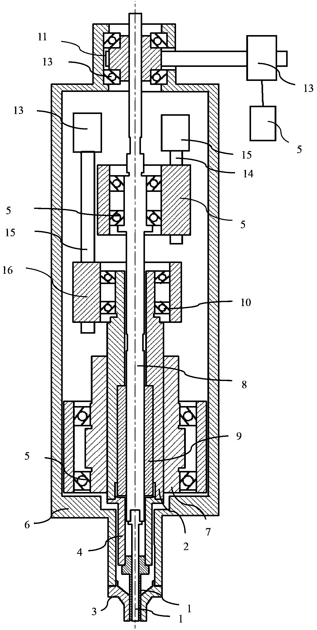
[0025] (1) Stirring pin 1 and shaft shoulder 2 of the stirring head can move in the opposite direction along the axial direction while rotating together, and the shaft shoulder 2 moves downward into the weld, and at the same time, stirring pin 1 moves along with the shaft shoulder 2 synchronously. The axial direction moves in the opposite direction, and the lower end surface of the jacket 3 of the stirring head is pressed against the welding seam position;

[0026] (2) During the welding process, the stirring needle 1, the shaft shoulder 2 and the jacket 3 of the stirring head remain in a relative position. Under the rotation and extrusion of the shaft shoulder 2, the weldme...


PUM


Abstract

The invention relates to a backfill type friction stir welding method and device. According to the technical scheme, a novel friction stir spot welding device is used for achieving backfill type keyhole-free welding. The method comprises that a stir head is pushed down to press a part to be machined, the position of an outer sleeve of the stir head is invariant, a shaft shoulder rotates at a high speed to stab into a welding bead, a stir needle moves far away from the welding bead direction, the shaft shoulder begins to perform welding after stabbing for certain depth into the welding bead, softened metal flows into space formed by the welding bead, the stir needle and the shaft shoulder, the shaft shoulder is withdrawn from the part to be welded, the stir needle pushes the metal in the space to press the part to be welded, and accordingly, a key hole is filled, welding is completed, and the stir head is unloaded and withdrawn. Compared with the prior art, the backfill type friction stir welding method and device have the advantages that uneven welding beads caused by key holes are eliminated, and the welding penetration depth evenness is guaranteed during discontinuous welding beads.

Description

technical field [0001] This patent relates to a backfilling friction stir welding method and its device, belonging to the technical field of friction stir welding. Background technique [0002] After the friction stir welding weldment is welded, a keyhole will be left at the end of the weld of the weldment. In order to eliminate the keyhole, a retractable friction stir welding welding device is usually used to achieve it. However, when the weld is an intermittent weld and requires a uniform penetration depth, the keyhole after welding cannot be eliminated by using a retraction device. Contents of the invention [0003] The present invention is a kind of backfill friction stir welding method and its device designed in view of the deficiencies in the above-mentioned prior art. Uniform penetration depth. [0004] The purpose of the present invention is achieved through the following technical solutions: [0005] The technical solution of the present invention proposes a ba...

Claims


Application Information

Patent Timeline
Patent Type & Authority Applications(China)
IPC IPC(8): B23K20/12
Inventor 柴鹏栾国红李明亮孙年俊杨模聪赵妍
Owner BEIJING AERONAUTICAL MFG TECH RES INST
Why Eureka
Try Eureka