Chassis structure of vehicle body of magnetic levitation vehicle

A technology of magnetic levitation and underframe, applied in the direction of underframe, railway car body, railway car body parts, etc., can solve the problem that the static strength and fatigue life of honeycomb aluminum floor cannot be accurately evaluated, and the flatness and straightness of the lower surface of the sliding table beam are not easy. Guarantee, poor sound insulation effect of car body, etc., to achieve the effect of convenient suspension, light weight and good sound insulation effect of chassis equipment

Active Publication Date: 2013-11-27
ZHUZHOU ELECTRIC LOCOMOTIVE CO
View PDF4 Cites 21 Cited by
  • Summary
  • Abstract
  • Description
  • Claims
  • Application Information

AI Technical Summary

Problems solved by technology

[0002] At present, the chassis of domestic maglev vehicles mostly adopts a frame structure, such as figure 1 As shown, that is, the underframe is a frame composed of welded skeleton beams intersected by crossbeams 12 and longitudinal beams 13. A honeycomb aluminum floor 14 is inlaid in the middle of the frame, and all underframe equipment is suspended on the crossbeams. The part is non-integral. The disadvantages of this scheme are: the rigidity of the car body is relatively weak, the flatness and straightness of the lower surface of the slide beam are not easy to guarantee (because the left and right slides are separated), the sound insulation effect of the car body is not good, and the parts The large quantity and large amount of welding are not conducive to the implementation of automatic welding. In addition, the static strength and fatigue life of the honeycomb aluminum floor cannot be accurately evaluated

Method used


Image

  • Chassis structure of vehicle body of magnetic levitation vehicle
  • Chassis structure of vehicle body of magnetic levitation vehicle
  • Chassis structure of vehicle body of magnetic levitation vehicle

Examples


Embodiment Construction

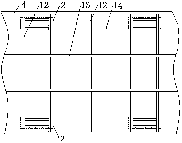
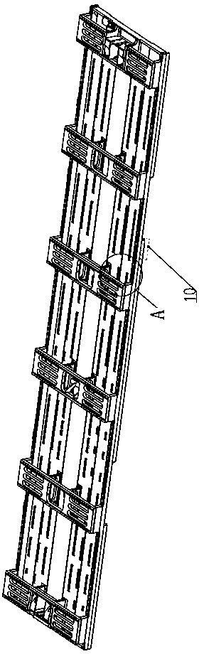
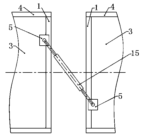
[0031] A maglev vehicle body underframe structure, see figure 2 and 4 As shown, the entire underframe structure is composed of a long floor 3, two underframe side beams 4, two underframe end beams 1, six sets of sliding platform beams 2, and transverse shock absorber mounting seats 5. The body underframe materials are all made of High-strength hollow extruded aluminum alloy maximizes weight reduction.

[0032] Among them, such as figure 2 and 4 As shown, the long floor 3 runs through from the beginning to the end, and is made of 5 (but not limited to 5) hollow extruded aluminum alloy profiles tailor-welded. The lower surface of the long floor 3 is designed with a C-shaped groove 6 for the suspension of equipment under the vehicle It is fixed with pipelines and cables, the front end and rear end of the long floor 3 are respectively connected with the end beams 1 of the second chassis, and the left and right sides of the long floor 3 are connected with the side beams 4 ...


PUM


Abstract

The invention discloses a chassis structure of a vehicle body of a magnetic levitation vehicle. The chassis structure of the vehicle body of the magnetic levitation vehicle aims at solving the problems that the existing chassis structures of vehicle bodies of vehicles are large in welding amount, multiple in part and insufficient in strength. The chassis structure of the vehicle body of the magnetic levitation vehicle comprises a square-shaped chassis frame which is formed by two chassis end beams and two chassis side beams through fixed connection; the two chassis side beams are connected through a long floor; the front end and the rear end of the long floor are connected onto the two chassis end beams; the lower portion of the chassis frame is provided with a plurality of groups of sliding platform beams; two ends of every group of sliding platform beams are fixed on the corresponding chassis side beams; the lower surface of every group of sliding platform beams is provided with a guide groove; the connecting positions of the two chassis end beams and the long floor are provided with horizontal damper installing bases. According to the chassis structure of the vehicle body of the magnetic levitation vehicle, the structural stiffness is large, the accuracy of the flatness and straightness of the sliding platform beams is high, the sound insulation effect is good, welding seams are less, and the chassis equipment is convenient to suspend.

Description

technical field [0001] The invention relates to a novel vehicle body underframe structure suitable for magnetic levitation vehicles, belonging to the technical field of rail vehicle manufacturing. Background technique [0002] At present, the chassis of domestic maglev vehicles mostly adopts a frame structure, such as figure 1 As shown, that is, the underframe is a frame composed of welded skeleton beams intersected by crossbeams 12 and longitudinal beams 13. A honeycomb aluminum floor 14 is inlaid in the middle of the frame, and all underframe equipment is suspended on the crossbeams. The part is non-integral. The disadvantages of this scheme are: the rigidity of the car body is relatively weak, the flatness and straightness of the lower surface of the slide beam are not easy to guarantee (because the left and right slides are separated), the sound insulation effect of the car body is not good, and the parts The large quantity and large amount of welding are not conduc...

Claims


Application Information

Patent Timeline
Patent Type & Authority Applications(China)
IPC IPC(8): B61F1/00B61F1/08B61D17/10
Inventor 苏永章张海波
Owner ZHUZHOU ELECTRIC LOCOMOTIVE CO
Why Eureka
Try Eureka