Wind driven generator

A technology for wind turbines and wind turbines, applied in wind turbines, wind energy power generation, wind turbine control, etc., can solve the problems of lack of circuit protection, rising costs, etc., and achieve strong economic applicability, load reduction, and total output power reduction. Effect

Inactive Publication Date: 2013-11-27
UNIV OF SHANGHAI FOR SCI & TECH
View PDF5 Cites 7 Cited by
  • Summary
  • Abstract
  • Description
  • Claims
  • Application Information

AI Technical Summary

Problems solved by technology

[0003] The anti-typhoon design of traditional wind turbines is often to thicken and thicken the central shaft to make it have greater bending strength, which will greatly increase the cost and lack protection for the circuit

Method used


Image

  • Wind driven generator
  • Wind driven generator
  • Wind driven generator

Examples


Embodiment approach 1

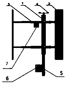
[0048] figure 1 It is the front view of the wind power generator involved in the present invention before the typhoon comes in the first embodiment;

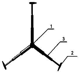
[0049] figure 2 It is a top view of the wind power generator involved in the present invention before the typhoon comes in Embodiment 1;

[0050] Such as figure 1 , 2 As shown, the wind power generator involved in the present invention includes: a pillar 5 fixed on the ground, a rotating shaft 1 fixed on the pillar and a wind wheel assembly rotating in a horizontal plane around the rotating shaft. The wind wheel assembly includes three rotating parts, and the rotating part Consists of: blades 2 and length-adjustable rods 3 . One end of the rod 3 is fixed to the rotating shaft 1, and the other end is fixed to the blade 2, and each blade is fixed by two rods;

[0051] The wind power generator involved in the present invention further includes: a driving device 7 , an anemometer 4 and a control device 6 . The driving device ...

Embodiment approach 2

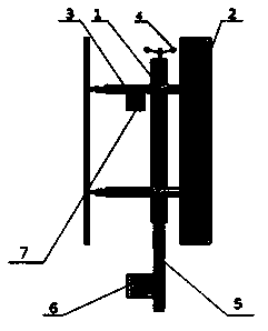
[0068] Image 6 It is the front view of the wind power generator involved in the present invention before the typhoon comes in the second embodiment;

[0069] Figure 7 It is the top view of the wind power generator involved in the present invention before the typhoon comes in the second embodiment;

[0070] Such as Image 6 , 7 Shown: the wind power generator that the present invention relates to comprises: the pillar 5 that is fixed on the ground, the rotating shaft assembly that is fixed on the pillar and the wind wheel assembly that rotates around the rotating shaft in the horizontal plane, and the wind wheel assembly includes at least two elastic The blade 2, a rod 3 with an adjustable length; the shaft assembly includes a shaft 1, a fixed block 7 and a fixed block 8. The blade 2 is arc-shaped in the vertical plane; one end of the blade 2 is fixed on the fixed block 7, and the fixed block 7 is fixed to the lower end of the rotating shaft 1; the other end of the blade ...


PUM


Abstract

The invention provides a wind driven generator which not only can protect a circuit but also can reduce cost. The wind driven generator comprises a strut, a rotating shaft and a wind wheel assembly, wherein the strut is fixed on the ground, the rotating shaft is fixed on the strut, and the wind wheel assembly rotates around the rotating shaft in the horizontal plane. The wind wheel assembly comprises at least two rotating components. Each rotating component comprises blades and at least one length-adjustable rod, wherein one end of each rod is fixed on the rotating shaft and the other end of each rod is fixed on each blade. When a typhoon comes, the rods in the wind wheel assembly stretch out and draw back in an adjusted mode to reduce the swept area of wind wheels, so that force application is reduced, total output power is lowered, the circuit can be protected, premature overload is avoided, and the effect that the wind driven generator runs safely under poor working conditions such as the typhoon and a violent typhoon is guaranteed; after the typhoon, the rods stretch out and draw back in the adjusted mode to return situ, therefore, the effect that the wind driven generator runs normally and safely again after the typhoon is achieved, the maximum utilization rate of the wind machine is effectively achieved while the mode of thickening the strut is got rid of, cost is reduced, and the wind driven generator has strong economic applicability.

Description

technical field [0001] The invention relates to a wind power generator, in particular to a vertical axis wind power generator. Background technique [0002] Currently, common types of vertical axis wind turbines include Darrieus-type wind turbines and H-type wind turbines. Under typhoons and strong typhoons, the central shaft of the wind turbine will be deformed. Most modern wind turbine designs adopt international standards (IEC 61400-1), but this standard generally only considers the operating conditions in Europe and North America, and does not include design requirements in tropical cyclone active areas. Therefore, many historical cases of wind turbine failure in tropical cyclone activities have been caused, resulting in great economic losses. It is estimated that by 2020, China's total offshore wind power installed capacity target will be 30GW, of which 40% of offshore wind turbines will face the risk of typhoons and strong typhoons. [0003] The anti-typhoon design ...

Claims


Application Information

Patent Timeline
Patent Type & Authority Applications(China)
IPC IPC(8): F03D3/06F03D7/06
CPCY02E10/74Y02E10/728
Inventor 高伟李春陈余陈晖叶舟聂佳斌李志敏吴攀魏远栾忠骏
Owner UNIV OF SHANGHAI FOR SCI & TECH
Why Eureka
Try Eureka