
Buffer tank structure for natural gas compressor

A buffer tank and compressor technology, applied in mechanical equipment, machines/engines, liquid variable capacity machinery, etc., can solve the problems of discontinuity, affecting the normal production and production personnel safety of natural gas compressors, cracks, etc., to simplify the stress , the effect of prolonging the time of fatigue failure

Inactive Publication Date: 2013-11-27
CHENGDU TIANYI NATURAL GAS COMPRESSOR MFG
View PDF6 Cites 2 Cited by
  • Summary
  • Abstract
  • Description
  • Claims
  • Application Information

AI Technical Summary

Problems solved by technology

[0003] However, the exhaust pressure of the existing natural gas compressor reaches the medium pressure or even high pressure range after multi-stage compression, and due to the discontinuity of the exhaust and suction of the piston compressor, the buffer tank and its connecting pipe are resonant in the gas column and excited in the pipe. Under the influence of stress and pipeline mechanical resonance, the possibility of cracks appearing in the heat-affected zone of the weld position in a short period of time is very high, which seriously affects the normal production of natural gas compressors and the safety of production personnel

Method used


Image

  • Buffer tank structure for natural gas compressor

Examples


Embodiment 1

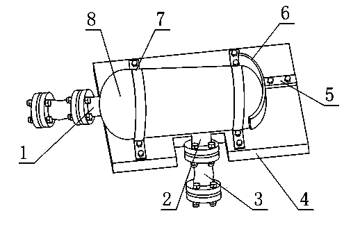
[0024] Such as figure 1 As shown, the buffer tank structure for natural gas compressors includes a buffer tank 8, an air outlet pipe 1 and an air inlet pipe 2. The buffer tank 8 is fixedly connected by a cylinder in the middle and heads at both ends. The air outlet pipe 1 It is fixedly connected to any head, the air inlet pipe 2 is fixedly connected to the cylinder body, and also includes a support plate 4 and two flexible pipes 3, and the two flexible pipes 3 are fixedly connected to the air outlet pipe 1 and the air inlet pipe 2 respectively , the support plate 4 is located below the buffer tank 8 , and the support plate 4 is fixedly connected to the buffer tank 8 .

[0025] The two flexible pipes 3 are set so that the buffer tank 8 is flexibly connected to the gas outlet of the upper stage and the inlet end of the next stage, so that the uneven exhaust of the upper stage and the uneven suction of the lower stage cause the buffer tank 8 to Most of the gas column resonance a...

Embodiment 2

[0027] The present embodiment is further limited on the basis of embodiment 1, as figure 1 As shown, at least two hoop bodies 7 are also included, and the buffer tank 8 is fixedly connected to the support plate 4 through the hoop bodies 7 .

[0028] The support plate 4 and the buffer tank 8 are connected in the form of a hoop, so that the contact area between the hoop body 7 and the buffer tank 8 is large, which is beneficial to reduce the degree of stress concentration of the interaction force between the buffer tank 8 and the support plate 4 .

[0029] It also includes an arc-shaped plate 6, which is fixedly connected with the support plate 4, and the arc-shaped plate 6 is in contact with the outer wall surface of the head opposite to the head connected with the air outlet pipe 1.

[0030] The provided arc plate 6 is used to counteract the recoil force of the gas discharged from the buffer tank 8 , which is beneficial to the stability of the buffer tank 8 fixed on the suppor...


PUM


Abstract

The invention discloses a buffer tank structure for a natural gas compressor. The buffer tank structure comprises a buffer tank, a gas outlet pipe and a gas inlet pipe. The buffer tank is formed by fixedly connecting a middle barrel and end sockets at two ends, the gas outlet pipe is fixedly connected with any one of the end sockets, and the gas inlet pipe is fixedly connected with the barrel. The buffer tank structure further comprises a supporting plate and two flexible pipes. The two flexible pipes are fixedly connected with the gas outlet pipe and the gas inlet pipe respectively, the supporting plate is arranged below the buffer tank, and the supporting plate is fixedly connected with the buffer tank. The buffer tank structure is favorable for reducing complex degree of stress on the buffer tank, the gas inlet pipe and the gas outlet pipe and the stress and prevents vibration of a higher compressing level and a lower compressing level of the buffer tank from being delivered to the buffer tank.

Description

technical field [0001] The invention relates to the field of natural gas compressor components, in particular to a buffer tank structure for a natural gas compressor. Background technique [0002] In order to avoid excessively high discharge gas temperature from natural gas compressors, reduce compressor power consumption, increase the utilization rate of cylinder volume and simplify the compressor structure, existing natural gas compressors generally adopt multi-stage compression, and there is a compressor between each stage. The natural gas buffer tank is used to eliminate or weaken the surge at the inlet of the next stage and when the suction volume of the next stage reaches its peak value, the suction port will not be too low due to excessive gas intake. [0003] However, the exhaust pressure of the existing natural gas compressor reaches the medium pressure or even high pressure range after multi-stage compression, and due to the discontinuity of the exhaust and suction...

Claims


Application Information

Patent Timeline
IPC IPC(8): F04B39/00
Inventor 孙伟余世春
Owner CHENGDU TIANYI NATURAL GAS COMPRESSOR MFG
Features
  • Generate Ideas
  • Intellectual Property
  • Life Sciences
  • Materials
  • Tech Scout
  • Unparalleled Data Quality
  • Higher Quality Content
  • 60% Fewer Hallucinations
Learn More