Installation method and disassembly method of a connecting bolt structure

A technology for connecting bolts and bolts, applied in the direction of connecting components, screws, threaded fasteners, etc., can solve the problems of not allowing large deformation, difficult to fasten objects, and low deformation performance of objects, and to simplify the fastening method. , the effect of expanding application space and improving work efficiency

Inactive Publication Date: 2015-11-25
青岛林川工程技术有限公司 +1
View PDF9 Cites 0 Cited by
  • Summary
  • Abstract
  • Description
  • Claims
  • Application Information

AI Technical Summary

Problems solved by technology

In some cases, the object to be fastened includes multiple layers, the deformation performance of the object is not high, large deformation is not allowed, and the opposite side has no operating space, at this time it is difficult to fasten the object with conventional bolts
[0003] For example, when surface demolition formwork is used to reinforce structures such as pier columns, the formwork often adopts lap joints instead of the flange butt joint form commonly used in steel formwork, and there is no operating space inside the formwork. In this case, conventional bolts unable to achieve its fastening purpose

Method used


Image

  • Installation method and disassembly method of a connecting bolt structure
  • Installation method and disassembly method of a connecting bolt structure
  • Installation method and disassembly method of a connecting bolt structure

Examples


Embodiment Construction

[0027] The present invention provides an installation method and a disassembly method of a connecting bolt structure. In order to make the purpose, technical solution and effect of the present invention clearer and clearer, the present invention will be further described in detail below. It should be understood that the specific embodiments described here are only used to explain the present invention, not to limit the present invention.

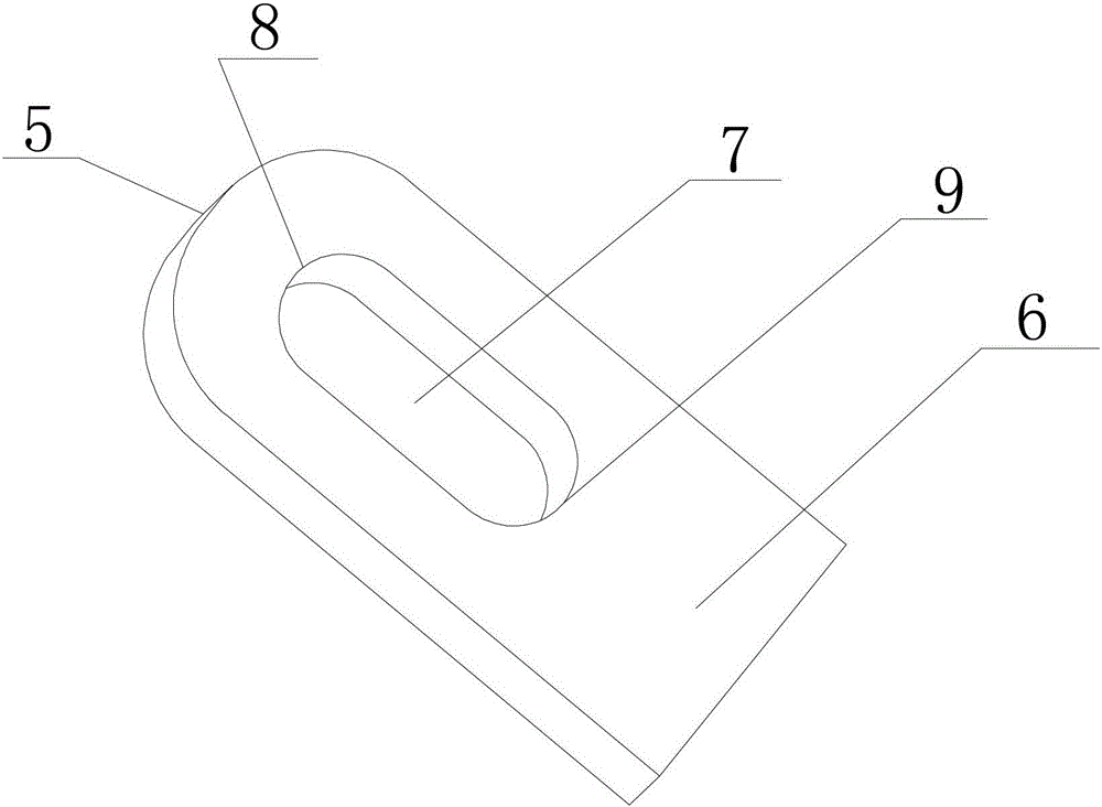
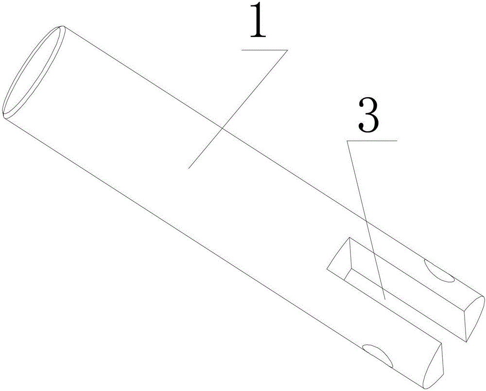
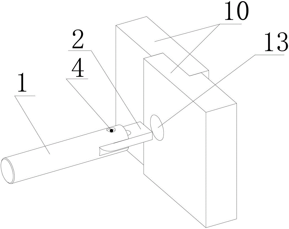
[0028] The invention provides a connecting bolt structure capable of post-mounting a screw rod, such as figure 1 , figure 2 and image 3 As shown, it includes a screw rod 1 and a fixed piece 2, and one end of the screw rod 1 is provided with a section of thread, and the other end is provided with a section of through notch 3, and the fixed piece 2 passes through a pin located in the through notch 3 The shaft 4 is connected to the screw 1, and the axis of the pin shaft 4 is perpendicular to the axis of the screw 1; the fixed piece 2 includ...


PUM


Abstract

The invention discloses a connecting bolt structure capable of mounting a screw rod afterwards as well as a mounting and dismounting method of the connecting bolt structure. The connecting bolt structure comprises the screw rod and a fixing piece, wherein a section of thread is arranged at one end of the screw rod, and a section of through notch is formed in the other end; the fixing piece is connected onto the screw rod through a pin shaft in the through notch; an axis of the pin shaft is perpendicular to that of the screw rod; the fixing piece comprises an arc end and a square end, a strip-shaped guide hole is formed in the position, between the arc end and the square end, of the fixing piece, and the pin shaft penetrates through the strip-shaped guide hole; and the fixing piece can surround the pin shaft, and swings and rotates to the position parallel to the axis of the screw rod or swings and rotates to the position perpendicular to the axis of the screw rod, and the fixing piece can generate displacement along the strip-shaped guide hole during the swinging and rotating process. With the adoption of the connecting bolt structure capable of mounting the screw rod afterwards as well as the mounting and dismounting method of the connecting bolt structure, the fastening for the edges of a fastened object is realized, the application space of the bolt is widened, and the work efficiency of an operator is improved.

Description

technical field [0001] The invention relates to a connecting bolt structure and a using method suitable for two or more layers of components that need to be fixed by bolts but has no operating space inside, and particularly relates to an installation method and a dismantling method of the connecting bolt structure. Background technique [0002] A bolt is a type of fastener consisting of a head and a screw (a cylinder with external threads), which needs to be matched with a nut to fasten two parts with through holes. But conventional bolt all is that screw rod is penetrated into bolt hole earlier, after installing the object that needs fastening, tighten nut outside, realizes fastening. In some cases, the object to be fastened includes multiple layers, the deformation performance of the object is not high, large deformation is not allowed, and there is no operating space on the opposite side. At this time, it is difficult to fasten the object with conventional bolts. [0003...

Claims


Application Information

Patent Timeline
Patent Type & Authority Patents(China)
IPC IPC(8): F16B35/06F16B35/04
Inventor 郭保林单川潘希峰陈培波宋亚伟卢建庆田建港
Owner 青岛林川工程技术有限公司
Why Eureka
Try Eureka