Heat-phonomotor driven by heat transfer through heat pipe

A thermoacoustic engine and heat pipe technology, applied in the direction of machines/engines, mechanisms that generate mechanical power, and mechanical equipment, can solve the problems of difficult heating power, pollution, noise, etc. The effect of expanding the application space

Inactive Publication Date: 2007-02-21
ZHEJIANG UNIV
View PDF0 Cites 20 Cited by
  • Summary
  • Abstract
  • Description
  • Claims
  • Application Information

AI Technical Summary

Problems solved by technology

Judging from the current research situation, for a thermoacoustic engine that uses electric heating tubes for direct contact heating, it is difficult to break through this heating power due to the limitation of the heating space.
Using gas heating technology to directly heat and drive the thermoacoustic engine through the high-temperature flue gas produced by burning natural gas or coal gas can increase the heat flux density to a certain extent, but it still cannot break through the limitation of the narrow heating space, and it will bring noise and damage to the thermoacoustic engine. pollution and other issues
Therefore, the reasonable selection of heating methods and the optimal design of heating devices are a major challenge for the practical application of thermoacoustic engines.

Method used


Image

  • Heat-phonomotor driven by heat transfer through heat pipe
  • Heat-phonomotor driven by heat transfer through heat pipe

Examples


Embodiment Construction

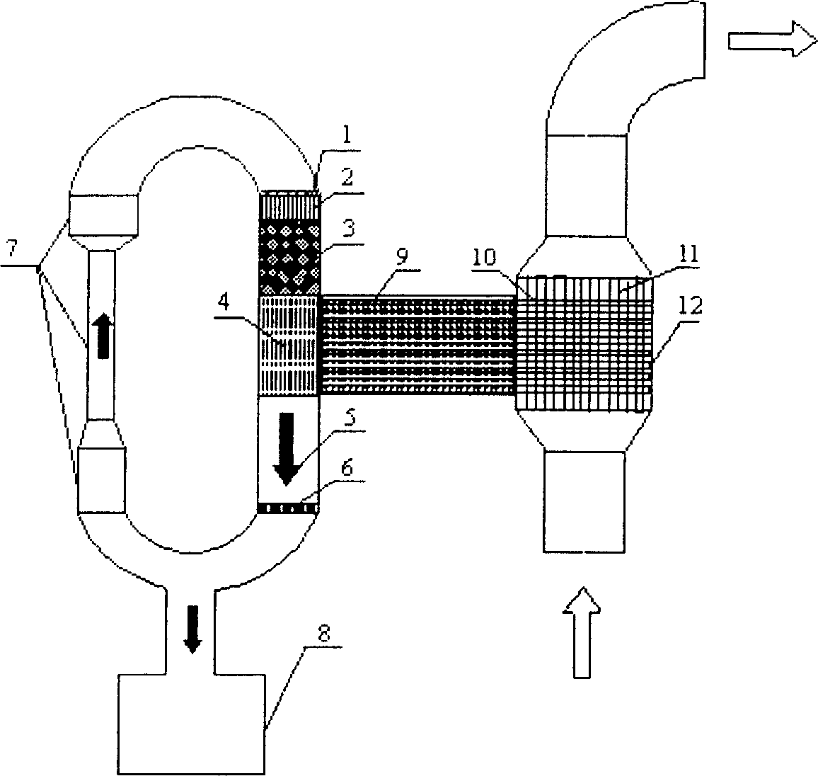
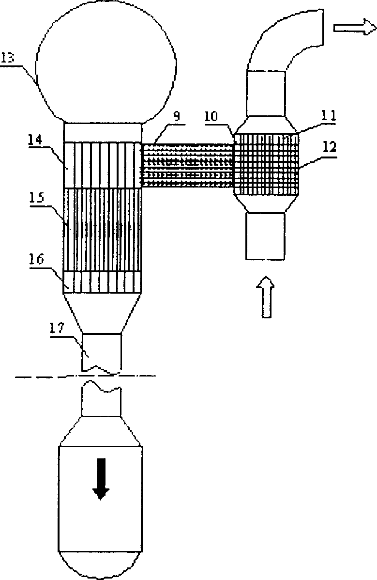
[0018] In fact, whether it is a traveling wave thermoacoustic engine or a standing wave thermoacoustic engine, heat pipe heating and driving technology can be used. In this patent, the traveling wave thermoacoustic engine and the standing wave thermoacoustic engine are used as examples for illustration.

[0019] like figure 1As shown, a thermoacoustic engine driven by heat pipe heat transfer has a traveling wave loop and a resonant branch 8. The traveling wave loop has a DC controller 1, a main cooler 2, a regenerator 3, and a heater connected in sequence. 4. Thermal buffer pipe 5 , sub cooler 6 , feedback loop 7 , the heater 4 of the thermoacoustic engine is connected to the heat exchanger 12 through the heat pipe 10 . The heat exchanger 12 is a shell-and-tube heat exchanger, and the shell side is filled with high-temperature flue gas or industrial steam.

[0020] The heat pipe heating device of the thermoacoustic engine includes the insulation layer 9 of the heat insulation...


PUM


Abstract

A thermo acoustic engine driven by heat conduction of heat tube consists of traveling-wave loop and resonant branch. It is featured as forming said traveling-wave loop by connecting in sequence of DC controller, master cooler, heat regenerator, heater, heat buffer tube, sub cooler and feedback loop; connecting heater of engine to heating source through heat tube.

Description

technical field [0001] The invention relates to a thermoacoustic engine, in particular to a thermoacoustic engine driven by heat transfer through a heat pipe. Background technique [0002] The thermoacoustic effect is a phenomenon of mutual conversion between heat and sound, that is, the time-averaged thermodynamic effect in the sound field. A thermoacoustic heat engine is essentially a device that converts or transmits heat energy and sound energy through the thermoacoustic effect. The thermoacoustic heat engine can establish a reasonable phase relationship between the velocity and pressure of the oscillating fluid without external mechanical means. Therefore, no mechanical transmission components are required, which greatly simplifies the structure of the system. According to the direction of energy conversion, thermoacoustic effects can be divided into two categories: one is to use heat to generate sound, that is, heat-driven acoustic oscillation, which is the working me...

Claims


Application Information

Patent Timeline
Patent Type & Authority Applications(China)
IPC IPC(8): F03G7/00
Inventor 孙大明邱利民
Owner ZHEJIANG UNIV
Why Eureka
Try Eureka