Crusher gear static pressure bearing mechanism

A technology of static pressure support and crusher, which is applied in the direction of gear lubrication/cooling, etc., which can solve the problems of inability to better protect large and small gears and supporting parts, unable to provide stable and long-lasting oil film protection, unstable oil supply and oil supply pressure, etc. problems, to achieve the effect of reliable performance, long service life and high rigidity of oil film

Inactive Publication Date: 2013-11-27
CITIC HEAVY INDUSTRIES CO LTD
View PDF6 Cites 2 Cited by
  • Summary
  • Abstract
  • Description
  • Claims
  • Application Information

AI Technical Summary

Problems solved by technology

Due to the long oil supply route and wide lubrication range of this oil supply lubrication method, when the lubricating oil reaches the static pressure support area of ​​the bevel gear, the oil supply quantity and oil supply pressure are often unstable. Once the crusher suddenly bears a large impact load, the mechanism will The vibration absorption ability is poor, and the large and small gears and supporting parts cannot be well protected, and the wearing of the supporting parts is accelerated, and in severe cases, it is easy to cause the phenomenon of burning tiles and shutting down
Although an annular oil storage tank and an oil discharge tank are provided on the lower end of the support, it is still unable to provide stable and long-lasting oil film protection due to the influence of the hydraulic oil supply method
At the same time, the static pressure support adopts the trapezoidal joint surface and several cylindrical pins to fix it, which also brings certain difficulties in processing and installation, and the practicability and economy are poor.

Method used


Image

  • Crusher gear static pressure bearing mechanism
  • Crusher gear static pressure bearing mechanism
  • Crusher gear static pressure bearing mechanism

Examples


Embodiment Construction

[0019] The technical solution of the present invention will be further described in detail below in conjunction with the accompanying drawings and embodiments.

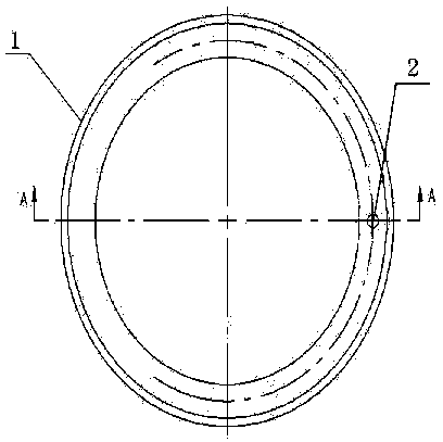
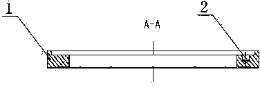
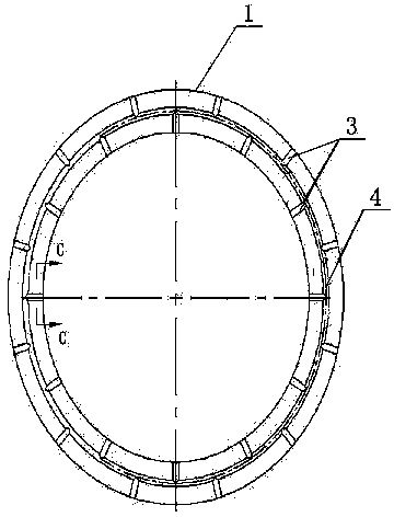
[0020] combine Figure 1-Figure 3 , a crusher gear static pressure support mechanism, including a static pressure support ring 1, the static pressure support ring 1 is a ring structure, and the inner hole is stepped, and the step surface of the inner hole is provided with positioning pin holes along the circumferential direction 2. An annular oil storage tank 4 is provided along the circumferential direction on the end surface of the small aperture of the static pressure support ring 1. The cross section of the annular oil storage tank 4 is wedge-shaped, and the annular oil storage tank 4 separates the small aperture end surface of the static pressure support ring 1 into inner On the ring surface and the outer ring surface, a number of radial oil unloading grooves 3 communicating with the annular oil storage tank 4 ar...


PUM


Abstract

The invention discloses a crusher gear static pressure bearing mechanism which comprises a static pressure bearing ring. The static pressure bearing ring is of an annular shape, the inner hole of the static pressure bearing ring is in a stepped shape, and dowel holes are formed in the stepped face of the inner hole in the circumferential direction. An annular oil storage tank is formed in the end face of a small hole diameter end of the static pressure bearing ring in the circumferential direction, the end face of the small hole diameter end of the static pressure bearing ring is divided into an inner ring face and an outer ring face through the annular oil storage tank, and a plurality of radial oil discharging tanks communicated with the annular oil storage tank are uniformly distributed in the inner ring face and the outer ring face in the circumferential direction respectively. According to the crusher gear static pressure bearing mechanism, the operating principle of hydrostatic static pressure bearing is utilized, namely a continuous and stable fluid pressure source is directly injected into a bearing face at the lower end of the static pressure bearing, fluid with definite pressure is supplied between friction surfaces, loads are borne with the help of static pressure of the fluid, gluing and fast abrasion of a bevel gear static pressure bearing piece and a backup washer are effectively prevented, and thus stability and reliability of transmission of a bevel gear are guaranteed.

Description

technical field [0001] The invention belongs to the technical field of hydraulic cone crushers and hydraulic gyratory crushers, and in particular relates to a crusher gear static pressure support mechanism. Background technique [0002] As we all know, in large-scale hydraulic cone (gyratory) crushers, the spiral bevel gear (hereinafter referred to as the bevel gear) is an important transmission mechanism for the crushing force of the crusher. Gluing or rapid wear due to friction often requires a structure with a large load-bearing capacity and low friction to adapt to the dynamic load and large load conditions of the broken parts. The static pressure support of the crusher is an important supporting mechanism of the bevel gear. The traditional static pressure support is fixed on the lower end surface of the bevel gear through the trapezoidal joint surface with a boss near the inner ring area on the upper end surface and several cylindrical pins. Lubricating oil is injected...

Claims


Application Information

Patent Timeline
Patent Type & Authority Applications(China)
IPC IPC(8): F16H57/04
Inventor 吴佳佳邱静雯邵彬赵经国张光霁刘慧芳王跃辉杨卫亮徐杰罗小强付晓蓉
Owner CITIC HEAVY INDUSTRIES CO LTD
Why Eureka
Try Eureka