Air chamber pressure relief device of combined type air conditioner unit system

A combined air-conditioning and pressure relief device technology, applied in valve devices, space heating and ventilation, heating and ventilation control systems, etc., can solve maintenance difficulties, unclear weight of valve discs in tubular valve seats, easy failure, etc. problems, to avoid the pressure of the negative pressure chamber is too low, to avoid the burnout of the fan motor, and to widen the applicable pressure range

Active Publication Date: 2013-11-27
CHENGDU EDRI AIR CONDITIONING MFG
View PDF4 Cites 3 Cited by
  • Summary
  • Abstract
  • Description
  • Claims
  • Application Information

AI Technical Summary

Problems solved by technology

This pressure relief valve has the following disadvantages: (1) Generally, it is a pipeline structure with complex structure, large volume and weight, and most of them require vertical installation
(2) Due to the use of pipeline structure, limited by processing, etc., the flow section is small
And the larger the pressure relief opening, the greater the pressure required, so the pressure relief is slow
(3) Its structural form makes it difficult to adjust the pressure relief pressure accurately
Users usually do not know the weight of the disc installed in the tubular valve seat, so it becomes difficult to change the weight of the weight by themselves to adjust the relief pressure precisely
(4) Since the disc is installed in the valve seat, maintenance is more difficult and it is easy to block
(5) Due to the complex structure and poor reliability, it is easy to fail
(5) The opening pressure of the existing pressure relief valve for pressure vessels is high, and the pressure of the air conditioning system cannot reach the working pressure value of the existing pressure relief valve for pressure vessels, so that it cannot be applied to the air conditioning system
This is also one of the reasons why the air chamber of the combined air conditioner unit in the prior art does not use a pressure relief valve.

Method used


Image

  • Air chamber pressure relief device of combined type air conditioner unit system
  • Air chamber pressure relief device of combined type air conditioner unit system
  • Air chamber pressure relief device of combined type air conditioner unit system

Examples


Embodiment Construction

[0031] The present invention will be further described below in conjunction with a preferred embodiment and accompanying drawings, so as to help understand the content of the present invention.

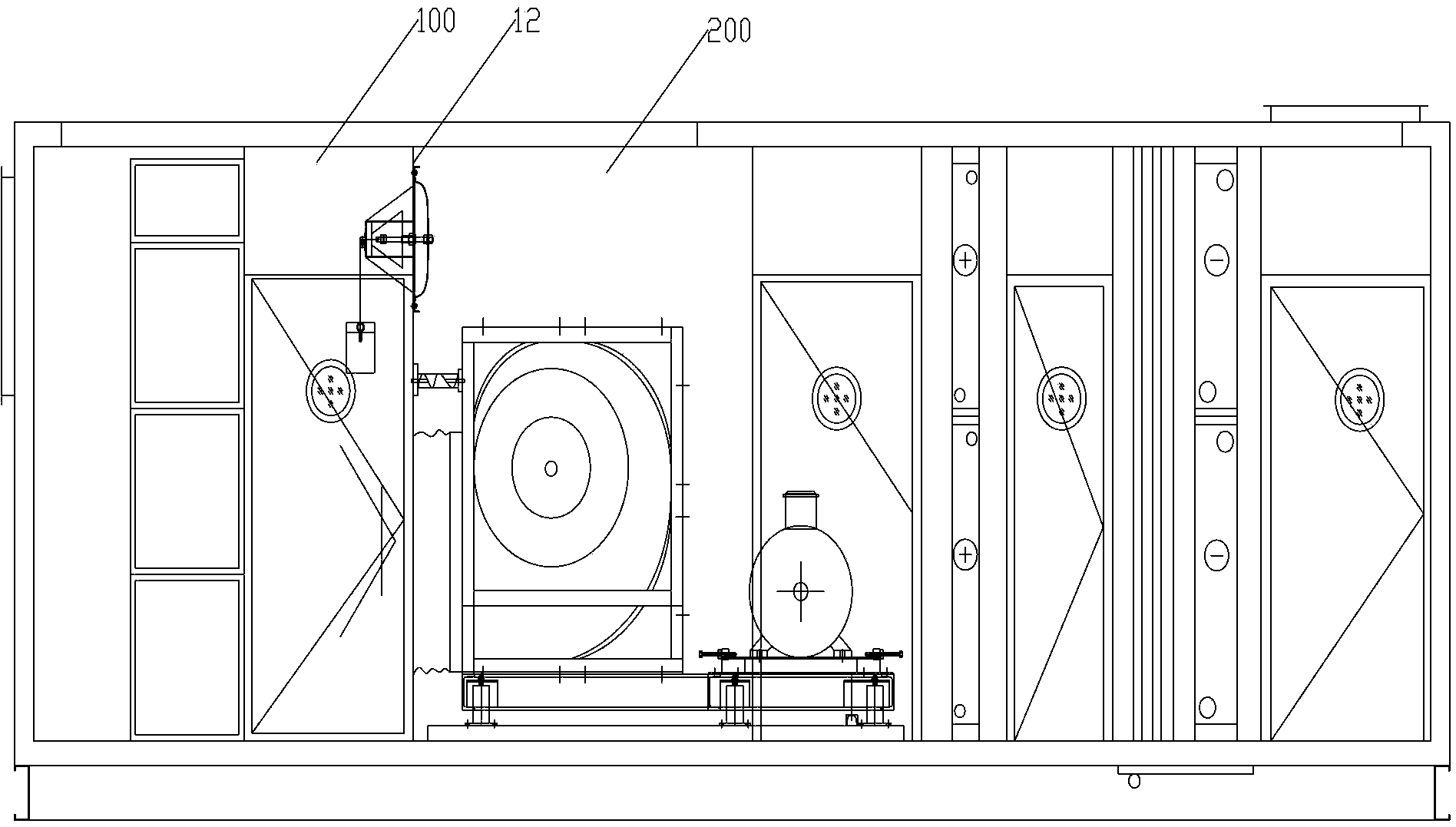
[0032] image 3 Shown is the air chamber device of the combined air conditioner unit, and the air chamber is divided into a positive pressure chamber 100 on the left side and a negative pressure chamber 200 on the right side in the figure by a vertical blocking plate 12 . Fans and drip trays are installed in the negative pressure chamber 200, which are used to pressurize the cold air generated by the refrigeration unit through the fans so as to be transported in the air ducts of the combined air-conditioning unit system. A diffuser and a filter are installed in the positive pressure chamber 100 to diffuse and purify the air.

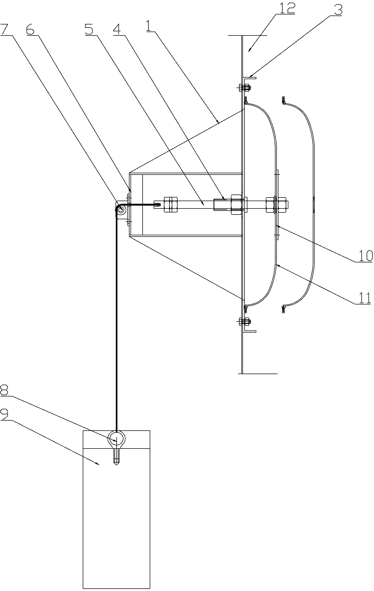
[0033] Such as figure 1 As shown, a combined air-conditioning unit system air chamber pressure relief device, the pressure relief valve installation hole open...


PUM


Abstract

The invention discloses an air chamber pressure relief device of a combined type air conditioner unit system. A pressure relief valve is mounted on a vertical plug board between a positive pressure chamber and a negative pressure chamber and a positive pressure chamber and comprises a bonnet, a valve seat, a pulley, a gravity block and a cable; a guide rod is arranged in the middle of the bonnet, a guide pipe is arranged in the middle of the valve seat, and a pressure relief hole is formed in a position on the periphery of the guide pipe, of the valve seat; the pulley is fixed on a support of the valve seat; the valve seat is mounted in the position of the pressure relief hole of the vertical plug board; the bonnet is located on one side of the negative chamber; the guide rod on the bonnet penetrates into the guide pipe on the valve seat; a pulley assembly mounted on the valve seat and the gravity block are located in the positive pressure chamber; one end of the cable is connected to the tail end of the guide rod of the bonnet, and the other end of the cable bypasses the pulley and is connected to the gravity block; and the gravity block is suspended freely. The device can avoid overpressure of the air chamber of the combined type air conditioner unit system, and is simple in structure, convenient to assemble and adjust and reliable in operation.

Description

technical field [0001] The invention relates to an air chamber safety protection device of a combined air conditioner unit, specifically a pressure relief protection device for avoiding overpressure of the air chamber, which can realize positive pressure chamber to negative pressure when the positive and negative pressure chambers of the combined air conditioner unit are overpressurized. Chamber pressure relief to balance the pressure to the normal range to ensure the safe operation of the device. Background technique [0002] In the combined air conditioning unit in the HVAC industry, the cooling capacity generated by the refrigeration unit is transported by the fan to the relevant room through the air duct in the form of cold air. The air outlet of the fan divides the two sides of the blocking plate into two air chambers. That is, the positive pressure chamber and the negative pressure chamber, the fan and the drip tray are installed in the negative pressure chamber, and t...

Claims


Application Information

Patent Timeline
Patent Type & Authority Applications(China)
IPC IPC(8): F16K17/12F24F11/00
Inventor 包峰刘红雨
Owner CHENGDU EDRI AIR CONDITIONING MFG
Why Eureka
Try Eureka