Center spring and helical blade rotor in heat exchange tube

A technology of helical blades and heat exchange tubes, applied in the field of central spring helical blade rotors, can solve the problems of weakening and strengthening heat transfer, anti-scaling and descaling performance, fast rotation speed, damage to the inner wall of heat exchange tubes, etc., to achieve anti-scaling Descaling and enhancing heat transfer, preventing the deposition of dirt, improving the effect of destruction

Active Publication Date: 2015-01-14
BEIJING UNIV OF CHEM TECH
View PDF9 Cites 0 Cited by
  • Summary
  • Abstract
  • Description
  • Claims
  • Application Information

AI Technical Summary

Problems solved by technology

In general, the spiral bond has the following main disadvantages: (1) The bond is a whole, which directly scratches the heat transfer tube and damages the inner wall of the heat transfer tube; (2) When the fluid flows to push the bond to rotate, it requires a large driving torque and consumes more (3) The service life of the bearing used for single-end fixing is short; (4) The effect of field synergy enhanced heat transfer generated by the bond is not significant
But the disadvantage is that when a certain fluid passes through, the rotation speed of the rotor is determined by the helix angle of the flight. When the flight lead is small, the rotation speed of the rotor is fast, and the resistance to the fluid increases accordingly; in order to solve this problem , China Patent Application No. 200910077378.0, the title of the invention is "A Unit Combined Enhanced Heat Transfer Device". The device is composed of a rotor, a support frame, a sleeve shaft and a connecting axis. The two ends of the tube are respectively fixed on the support frame, and multiple rotors are mounted on the connecting axis. The rotor is composed of a spoiler blade, a hinge structure, and a tail screw drive blade. This structure can significantly reduce the flow resistance of the fluid in the tube. , reduce wear and prolong the service life of the rotor, but because the central part of the structure of the rotor is a hollow structure, it weakens the enhanced heat transfer and anti-scaling and descaling performance in the central mainstream area

Method used


Image

  • Center spring and helical blade rotor in heat exchange tube
  • Center spring and helical blade rotor in heat exchange tube
  • Center spring and helical blade rotor in heat exchange tube

Examples


Embodiment Construction

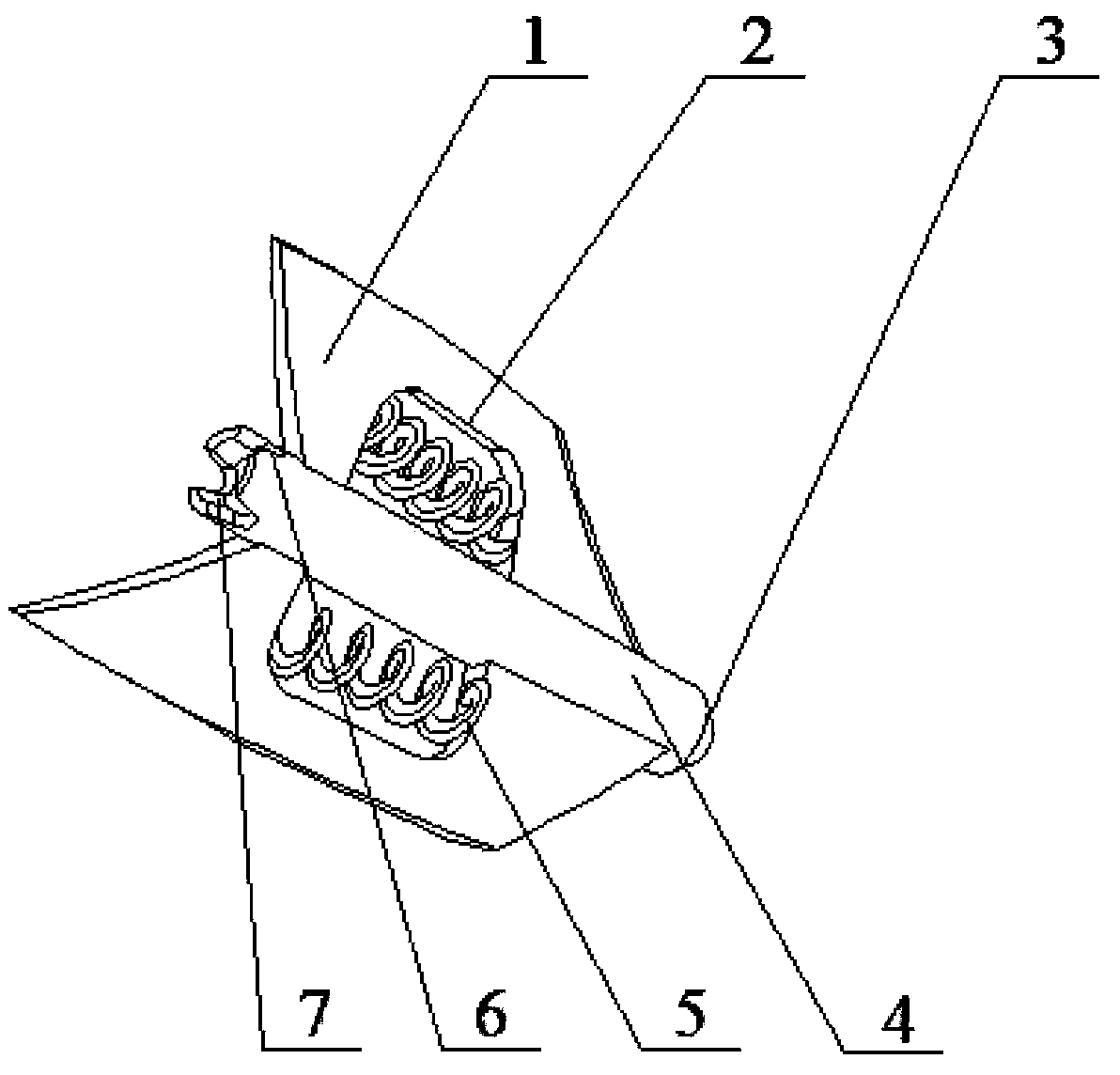
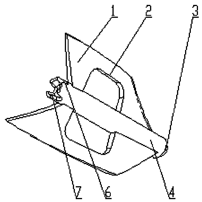
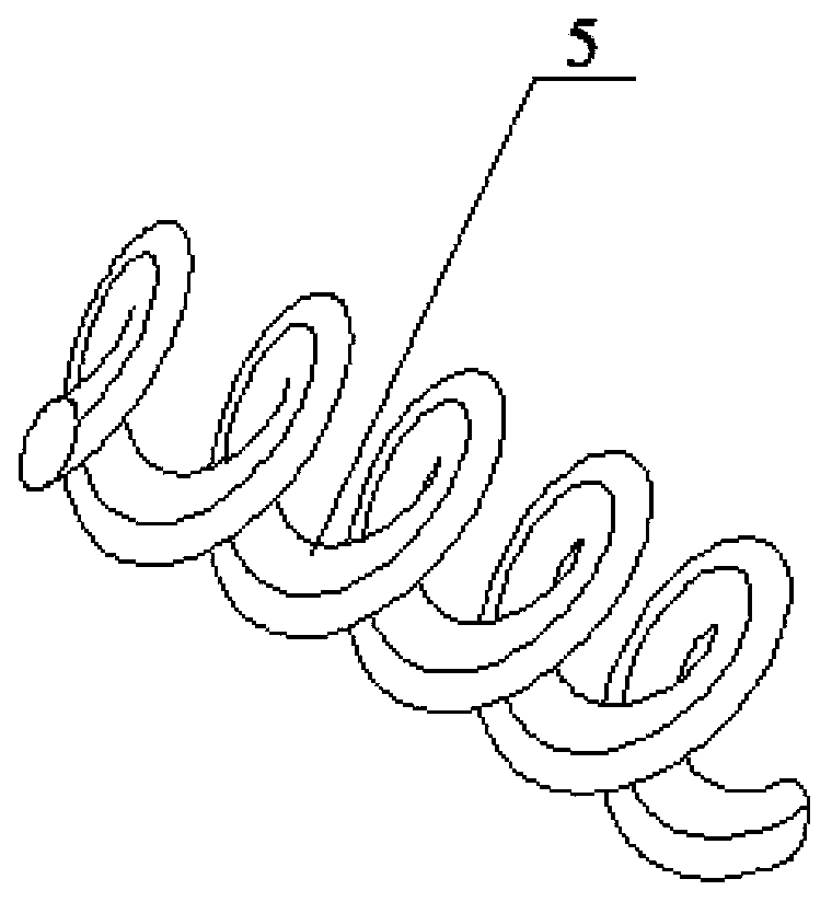
[0019] Such as Figure 4 As shown, the present invention relates to an implementation method of a central spring helical vane rotor in a heat exchange tube. The enhanced heat transfer device includes a rotor, a stopper 8, a heat exchange tube 9, a pendant 10 and a rotating shaft 11. Several rotors pass through The rotating shafts 11 are connected in series, and the limiting member 8 divides the plurality of rotors into several groups of rotor strings. The pendant 10 is fixed on both ends of the heat exchange tube 9, and the two ends of the rotating shaft 11 are respectively fixed on the pendant 10. The rotor of the present invention is composed of A certain number of hollow blades 1 are fixed on the surface of the hollow shaft 4. The surface of the blades is provided with a hollow structure 2 and a coil spring 5. The hollow shaft 4 is also provided with a ball-and-socket boss 3, a ball-and-socket recess 7 and a The hole 6 that the inner hole of the hollow shaft communicates wi...


PUM


Abstract

The invention relates to a center spring and helical blade rotor in a heat exchange tube. The rotor mainly comprises a hollow shaft, hollowed-out blades and helical springs. The hollowed-out blades are positioned on the surface of the hollow shaft, the outer diameter of each hollowed-out blade is smaller than the inner diameter of the heat exchange tube, the hollowed-out blades are smooth in surface and helically shaped around the hollow shaft, and a hollowed-out structure is arranged on the surface of each hollowed-out blade so as to reduce contact area of fluid and the rotor blades and reduce pressure loss when the fluid flows through the rotor. In order to reduce flow resistance of the fluid in the tube and further enhance strengthened heat transfer and self-cleaning performance of the hollowed-out portions, the helical springs are arranged in hollowed-out structures at the centers of the blades. The helical springs are arranged in the hollowed-out structures at the centers of the blades, so that tangential and radial movements of fluid regions in the hollowed-out structures are enabled to be strengthened in the process that the helical springs rotates with the rotor, a turbulence effect in the hollowed-out regions is further improved, and functions of scale prevention, descaling and strengthened heat transfer are further realized.

Description

technical field [0001] The invention relates to an interpolation element for enhancing heat transfer and anti-fouling and decontamination in heat exchange tubes used in shell-and-tube heat exchangers, heat exchange reactors and other equipment, in particular to an interpolation element that uses the heat transfer fluid inside the heat exchange tube as the Power, low energy consumption and high efficiency central spring helical vane rotor that realizes self-cleaning and enhanced heat transfer function. Background technique [0002] Energy saving and emission reduction is a key technology that the whole world attaches great importance to. It is applied to many heat exchangers in many fields such as petroleum, chemical industry, thermal power, nuclear power, metallurgy, light industry, aviation devices and marine vehicles, among which the most Shell-and-tube heat exchangers are widely used, but there are common problems of fouling and fouling in the inner walls of these heat ex...

Claims


Application Information

Patent Timeline
Patent Type & Authority Patents(China)
IPC IPC(8): F28F13/12F28G3/00
Inventor 杨卫民张震阎华
Owner BEIJING UNIV OF CHEM TECH
Why Eureka
Try Eureka