Visual intersected fracture flowing water grouting test device and method

A cross-crack and grouting test technology, which is applied in the direction of fluid dynamics test, measuring device, machine/structural component test, etc., can solve the problems of small size, inability to simulate dynamic water conditions, small adjustment range of crack surface width, etc. achieve large size

Active Publication Date: 2013-11-27
INST OF ROCK AND SOIL MECHANICS - CHINESE ACAD OF SCI
View PDF5 Cites 58 Cited by
  • Summary
  • Abstract
  • Description
  • Claims
  • Application Information

AI Technical Summary

Problems solved by technology

[0004] In the prior art, "Visual test device for crack grouting under complex conditions" discloses a simulation test device for grouting under complex crack conditions, and correlates the test method of grouting diffusion under complex crack conditions and loading conditions However, the condition of the single fracture surface in the device is quite different from the seepage path of the intersecting fracture network in the actual fractured rock mass. The fracture surface cannot adjust the inclination angle, and the adjustment range of the fracture surface width is small. Relatively small, there is a more obvious boundary effect when simulating slurry diffusion in fractured rock mass
"Gouting Diffusion Test Device" discloses a grouting test simulation device, which describes the test method of grouting diffusion in a single fracture surface, but it cannot simulate the dynamic water conditions under complex fracture network conditions, and the grouting process does not Realize the whole process of visualization and automatic collection of important parameters such as flow velocity and seepage pressure, and the simulation effect of the actual grouting situation on site is not ideal

Method used


Image

  • Visual intersected fracture flowing water grouting test device and method
  • Visual intersected fracture flowing water grouting test device and method
  • Visual intersected fracture flowing water grouting test device and method

Examples


Embodiment Construction

[0044] Below in conjunction with the accompanying drawings, the visual cross-crack dynamic water grouting test device and test method of the present invention will be further described in detail:

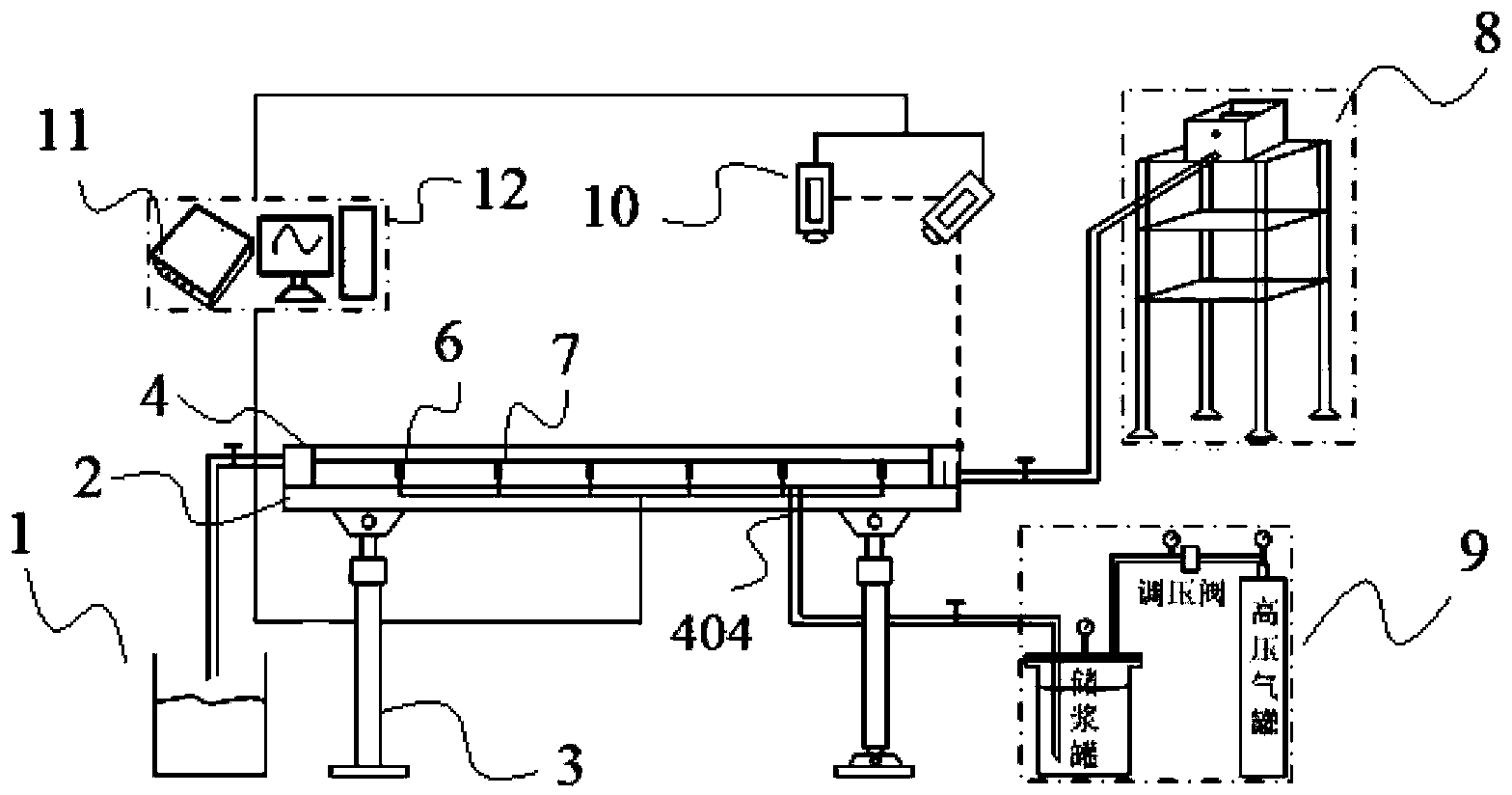
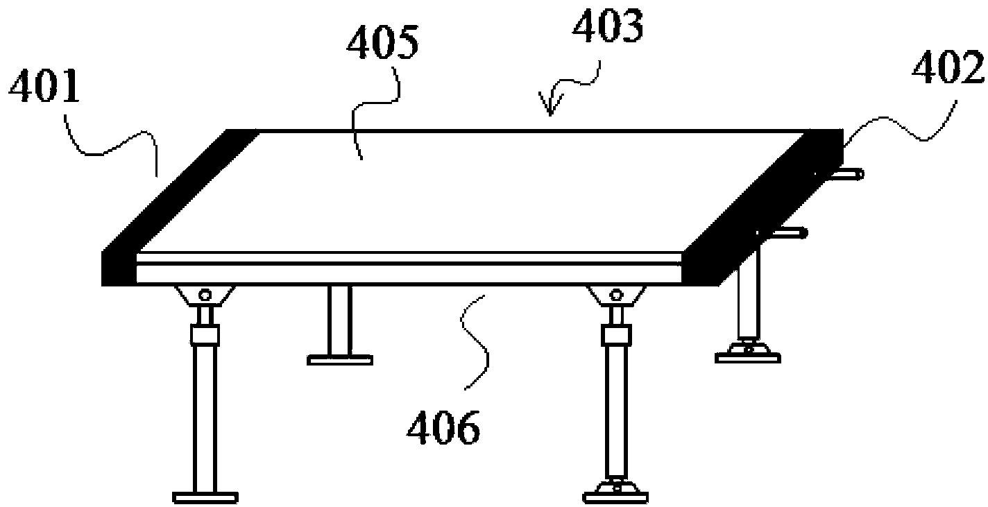
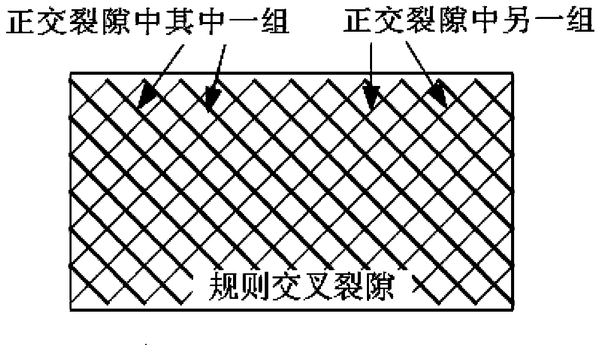
[0045] A visual cross-crack dynamic water grouting test device, including a grout collection device 1, and a cross-crack platform 2, the cross-crack platform 2 includes a support frame 3, a cross-crack test chamber 4 set on the support frame 3, and a cross-crack test chamber 4 set on the cross-crack The cross crack 5 on the inner wall of the crack test chamber 4, the flow rate sensor 6 arranged in the cross crack test chamber 4 and the pressure sensor 7 arranged in the cross crack test chamber 4;

[0046] It also includes a dynamic water supply device 8 for injecting water into the cross-crack test chamber 4 and an air pressure grouting device 9 for grouting the cross-crack test chamber 4, the cross-crack test chamber 4 is connected to the slurry collection device 1,

[0047] Both t...


PUM


Abstract

The invention discloses a visual intersected fracture flowing water grouting test device and method. The visual intersected fracture flowing water grouting test device comprises a grout collection device and further comprises an intersected fracture platform. The intersected fracture platform comprises supporting frames, an intersected fracture test room arranged on the supporting frames, intersected fractures arranged on the inner wall of the intersected fracture test room, flow sensors arranged inside the intersected fracture test room, and pressure sensors arranged inside the intersected fracture test room. The visual intersected fracture flowing water grouting test device further comprises a flowing water supply device used for injecting water for the intersected fracture test room and an air pressure grouting device used for grouting for the intersected fracture test room, and the intersected fracture test room is connected with the grout collection device. The visual intersected fracture flowing water grouting test device and method can achieve grouting simulation test and analysis under the conditions of the intersected fractures and flowing water.

Description

technical field [0001] The invention relates to a test device and a test method for a cross-crack dynamic water grouting model test, in particular to a visual cross-crack dynamic water grouting test device under consideration of the influence of dominant seepage channels. It is suitable for simulating the grouting process under the condition of dynamic water in complex fracture network, and studying the law of grouting diffusion and the mechanism of dynamic water sealing. Background technique [0002] In the process of constructing tunnels and underground projects in areas with rich groundwater or karst areas, the construction often faces the challenges of structure anti-seepage and ground reinforcement. The grouting method is a water blocking reinforcement measure widely used in engineering practice. Effective grouting under dynamic water conditions can achieve the effect of water blocking and reinforcement. On the one hand, there are different levels of fracture networks ...

Claims


Application Information

Patent Timeline
Patent Type & Authority Applications(China)
IPC IPC(8): G01M10/00
Inventor 陈卫忠袁敬强杨建平谭贤君杨典森
Owner INST OF ROCK AND SOIL MECHANICS - CHINESE ACAD OF SCI
Why Eureka
Try Eureka