
Laser tracker based method for achieving optical system axis through and center alignment

A laser tracker and optical system technology, applied in optics, optical components, optical devices, etc., can solve the problems of reduced precision, cumbersome operation procedures, low efficiency, etc., to improve work efficiency and precision, avoid complicated processes, operations, etc. Simple and fast effects

Inactive Publication Date: 2013-11-27
INST OF OPTICS & ELECTRONICS - CHINESE ACAD OF SCI
View PDF7 Cites 17 Cited by
  • Summary
  • Abstract
  • Description
  • Claims
  • Application Information

AI Technical Summary

Problems solved by technology

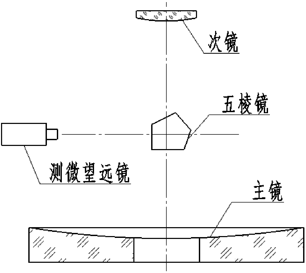
This method has several obvious disadvantages: 1. The operation process is cumbersome and the efficiency is low; 2. The accuracy is reduced due to the reference transfer; 3. The machining accuracy of the pentaprism has a great influence on the entire assembly accuracy

Method used


Image

  • Laser tracker based method for achieving optical system axis through and center alignment
  • Laser tracker based method for achieving optical system axis through and center alignment
  • Laser tracker based method for achieving optical system axis through and center alignment

Examples


Embodiment Construction

[0017] The specific implementation manners of the present invention will be further described in detail below in conjunction with the accompanying drawings.

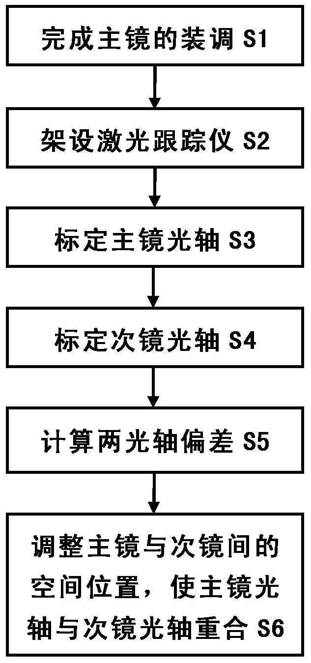
[0018] Such as figure 1 It shows the flow of the method of centering the optical system through the axis based on the laser tracker, and the method is completed through the following steps:

[0019] Step S1: Assemble and adjust the primary mirror and secondary mirror of the optical system.

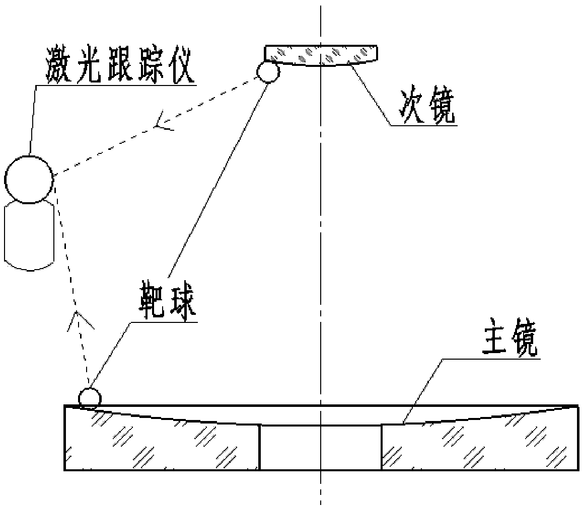
[0020] Step S2: Set up the laser tracker. Set up the laser tracker at a position where the primary mirror and the secondary mirror can be measured at the same time, and ensure that the laser tracker is stable.

[0021] Step S3: Move the target ball on the primary mirror, and use the laser tracker to calibrate the optical axis of the primary mirror. The target ball moves on the primary mirror, and the laser tracker is used to measure the moving space trajectory of the target ball, and the spatial geometric characteristics of the p...


PUM


Abstract

The invention discloses a laser tracker based method for achieving optical system axis through and center alignment. The method comprises the steps that S1, a primary mirror and a secondary mirror of an optical system are assembled and adjusted; S2, a laser tracker is arranged; S3, a target ball is moved on the primary mirror, and the optical axis of the primary mirror is calibrated through the laser tracker; S4, the target ball is moved on the secondary mirror, and the optical axis of the secondary mirror is calibrated; S5, the size and the direction of the space deviation between optical axis of the primary mirror and the optical axis of the secondary axis are calculated; S6, the space position between the primary mirror and the secondary mirror is adjusted according to the size and the direction of the space deviation to ensure that the optical axis of the primary mirror and the optical axis of the secondary mirror coincide. The laser tracker based method for achieving optical system axis through and center alignment solves the problems that tools in the prior are complex, tedious in operation process and large in datum error, and is easy to operate, safe and efficient.

Description

technical field [0001] The invention belongs to the field of optical installation and adjustment, and relates to a method for centering an optical system through a shaft, in particular to a method for centering an optical system through a shaft based on a laser tracker. Background technique [0002] Optoelectronic equipment usually consists of a primary mirror, a secondary mirror, and an imaging system behind it. If the optical axes of the primary mirror and the secondary mirror do not coincide, the primary and secondary mirror systems will produce large coma, which will seriously affect the image quality of the system. Therefore, in the optical calibration process of optoelectronic equipment, certain measures will be taken to ensure the coincidence of the optical axis of the primary mirror and the optical axis of the secondary mirror. [0003] Existing technical methods for adjusting the coincidence of the optical axis of the primary mirror with the optical axis of the seco...

Claims


Application Information

Patent Timeline
Patent Type & Authority Applications(China)
IPC IPC(8): G02B7/00G01B11/26
Inventor 徐祺瑞章明古斌马天梦
Owner INST OF OPTICS & ELECTRONICS - CHINESE ACAD OF SCI
Learn More