Flexible energizing hose

A hose and soft plastic technology, applied in the direction of hose, extendable conductor cable, extendable conductor, etc., to achieve the effect of safe and reliable electrification, easy to clean, and not easy to wear

Inactive Publication Date: 2013-11-27
JINHUA CHUNGUANG RUBBER & PLASTIC HOSE
View PDF4 Cites 5 Cited by
  • Summary
  • Abstract
  • Description
  • Claims
  • Application Information

AI Technical Summary

Problems solved by technology

[0008] Compared with the prior art, the present invention not only maintains the free and easy function of the existing telescopic hose, but also has the advantages of being not

Method used


Image

  • Flexible energizing hose
  • Flexible energizing hose
  • Flexible energizing hose

Examples


Example Embodiment

[0019] Embodiment one

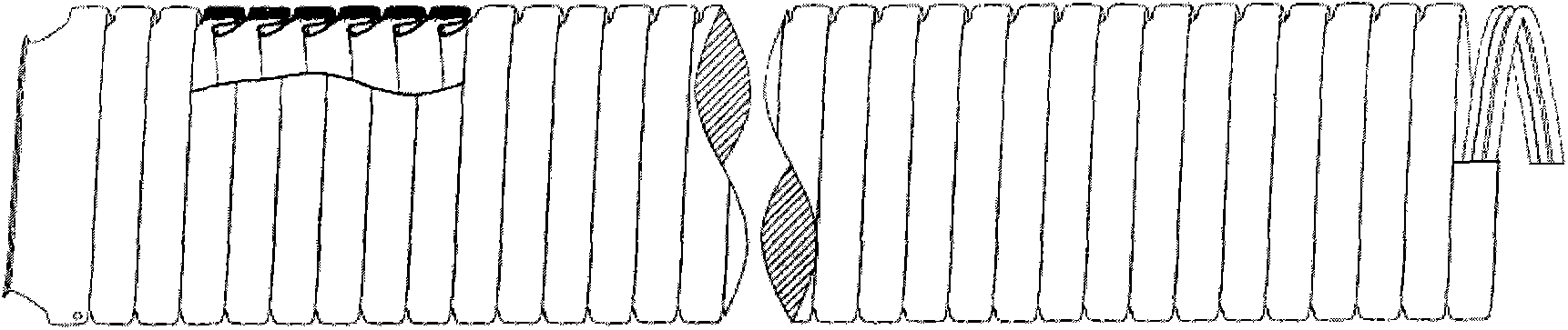
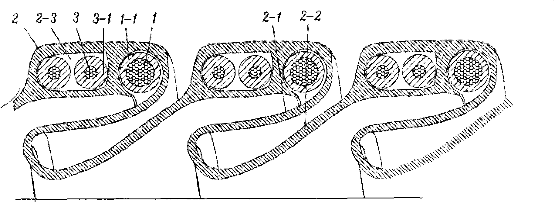
[0020] The retractable electrified hose of this embodiment is as figure 1 , 2 As shown, it includes a support 1 , a cladding 2 and two wires 3 , and the support 1 is composed of copper-clad steel wire bars spirally coiled along the length of the hose. The covering part 2 is composed of a sheet-shaped soft plastic strip coiled in the same direction with the support part 1 as the skeleton. The middle section of the sheet-shaped soft plastic strip has a containing cavity 2-3 that surrounds two wires 3 therein. The containing cavity 2 -3 is located between two adjacent ribs coiled in a spiral, and the left wing 2-1 and the right wing 2-2 respectively extend from both sides of its section. The wire 3 is wrapped with an insulating layer 3-1. After the wrapping part 2 is coiled, the edges of the adjacent left wing 2-1 and right wing 2-2 are hermetically bonded. When the hose is in a contracted state, the adjacent left and right wings 2-1 and 2-2 are folded...

Example Embodiment

[0021] Embodiment two

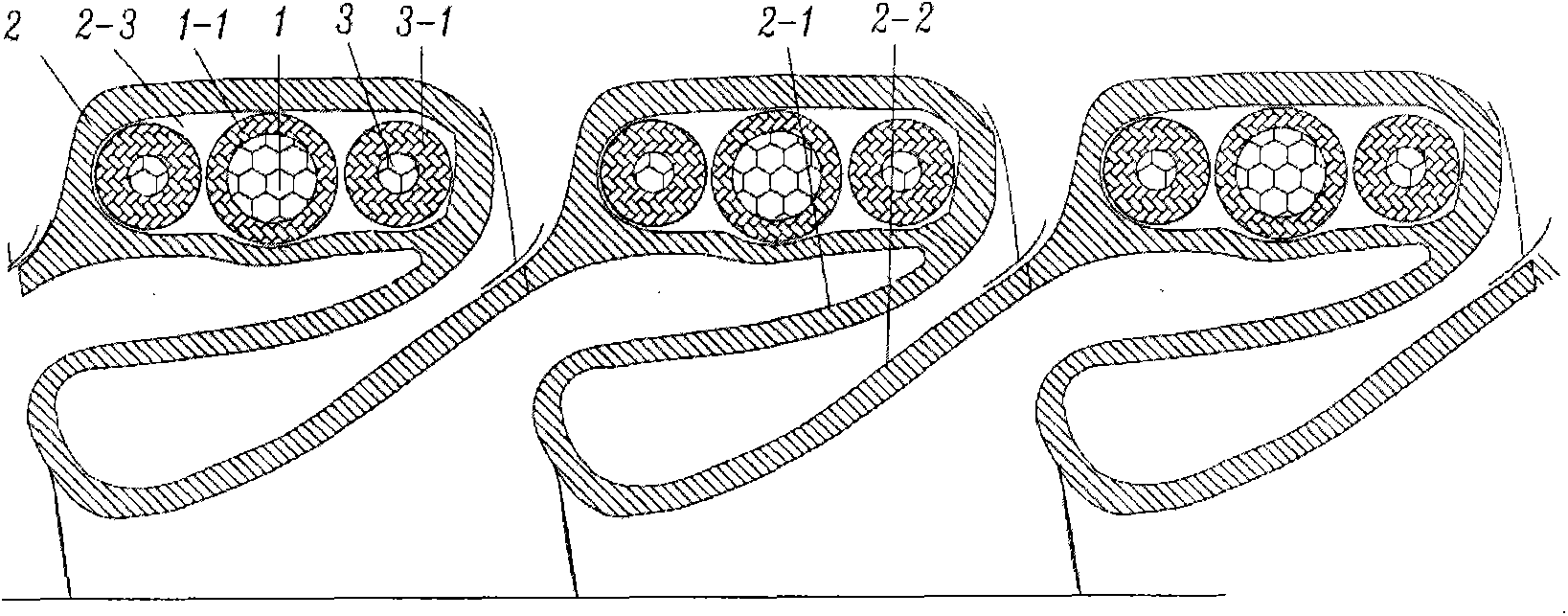
[0022] The retractable electrified hose of this embodiment is as image 3 As shown, the basic structure of the present embodiment is similar to that of the first embodiment, the difference is that the containing cavity 2-3 encloses the two wires 3 and the ribs therein. The two wires 3 are respectively located on both sides of the rib serving as the support member 1 and the signal line.

Example Embodiment

[0023] Embodiment three

[0024] The retractable electrified hose of this embodiment is as Figure 4 As shown, its basic structure is also similar to the first embodiment, the difference is that the containing cavity 2-3 surrounds two wires 3 and one of the two adjacent ribs.

[0025] To sum up, the above-mentioned embodiment has the following significant advantages:

[0026] 1) It not only maintains the free and easy expansion and contraction of the telescopic hose, but also because the covering part is folded in the support frame, it is not easy to wear and the appearance is easy to clean.

[0027] 2) More than two wires or copper-plated (coated) steel wires can be wrapped in the containment cavity between the supporting frames, thereby forming an effective double-layer protection outside the original wire protection layer, making the power supply safer and more reliable, and effectively meeting Standards such as IEC and UL.

[0028] 3) The process is practical and cost-e...


PUM


Abstract

The invention relates to a flexible energizing hose, and belongs to the technical field of hoses. The flexible energizing hose comprises a supporting piece, wrapping pieces and at least two guide lines. The supporting piece is formed by coiling rib strips in a spiral mode in the length direction of the hose. The wrapping pieces are formed by coiling sheet-shaped soft plastic strips in the same direction with the supporting piece as a framework. The middle of the section of each sheet-shaped soft plastic strip is provided with a containing cavity which contains the at least two guide lines, the two sides of the section of each sheet-shaped soft plastic strip extend to form a left wing and a right wing respectively, and the edges of the adjacent left wing and the right wing are sealed and combined after each wrapping piece is coiled. When the hose is in a shrinkage state, the adjacent left wing and the right wing are mutually folded, and an inner spiral folded wall inside the supporting framework is formed. Not only does the flexible energizing hose keep the function that an existing flexible hose can be flexible easily, but also due to the fact that the wrapping pieces are evenly placed in the spiral supporting framework and are folded in the supporting framework, the flexible energizing hose has the advantages of being not prone to being abraded, easy to clean and the like, the effective double-layer protection is obtained, and the energization is safer and more reliable.

Description

technical field [0001] The invention relates to a telescopic hose, in particular to a telescopic electrified hose, which belongs to the technical field of hoses. Background technique [0002] Existing stretchable plastic hoses are made of plastic-coated steel wire reinforcements as the skeleton and soft plastic as the outer layer of the hose through a winding process, and usually only have a stretching function. [0003] The search found that the U.S. Patent No. US7735523 discloses a telescopic electrified hose, which includes a support, a covering, and a set of wires. The support is formed by coiling strips of material along the long axis with intervals. The covering consists of a thermoplastic material covering the spacer and part of the support and is folded outwards in the area of ​​the spacer, the wires being located between the layers of thermoplastic material. Its advantage is that it properly solves the problem of power supply from one end of the hose to the other e...

Claims


Application Information

Patent Timeline
IPC IPC(8): H01B7/06H01B7/17H01B7/18H01B7/22
CPCF16L11/12H02G3/0462H02G11/006A47L9/248
Inventor 陈正明张文永吴剑凯
Owner JINHUA CHUNGUANG RUBBER & PLASTIC HOSE
Why Eureka
Try Eureka