
Closed reduction surgical frame for tibial fracture of patient

A surgical frame and tibia technology, applied in the directions of surgery, medical science, etc., can solve the problems of maintaining instability, x-ray opacity, and hindering x-ray examinations in different directions, and achieves the effect of simple structure and easy operation.

Inactive Publication Date: 2013-12-04
董文伟 +1
View PDF8 Cites 5 Cited by
  • Summary
  • Abstract
  • Description
  • Claims
  • Application Information

AI Technical Summary

Problems solved by technology

Compared with the reduction mode of parallel tibial shaft traction, the device requires more force under the same traction force, which is likely to cause compression of the popliteal vascular nerve and traction injury of the common peroneal nerve, and the direction perpendicular to the tibial shaft The component force is also easy to cause the front and back displacement of the fracture end
At the same time, the fixed distal femoral bracket structure cannot adjust the angle of the knee joint according to the needs of the operation. Due to the lack of a knee flexion maintenance device, it is necessary to hold the flexion state of the knee joint for a long time during traction and reduction, which is prone to maintenance instability
And the opacity of the device to x-rays makes it hinder x-ray examinations in different directions during the fracture reduction process
Therefore, the wide application of this resetting device in clinic is limited.

Method used


Image

  • Closed reduction surgical frame for tibial fracture of patient
  • Closed reduction surgical frame for tibial fracture of patient
  • Closed reduction surgical frame for tibial fracture of patient

Examples


Embodiment Construction

[0019] Below in conjunction with accompanying drawing and embodiment the present invention is further described:

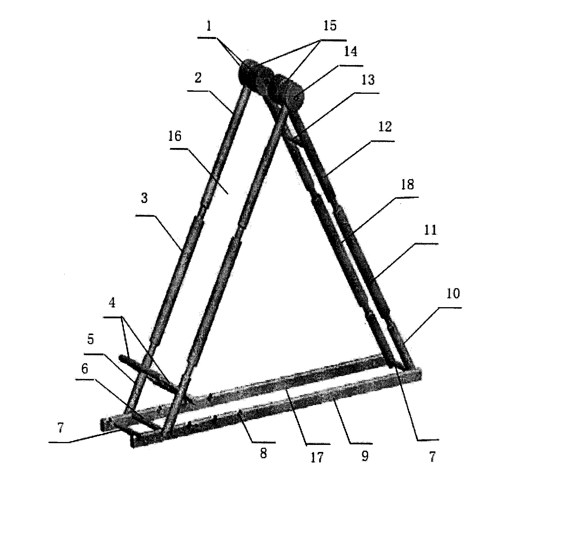
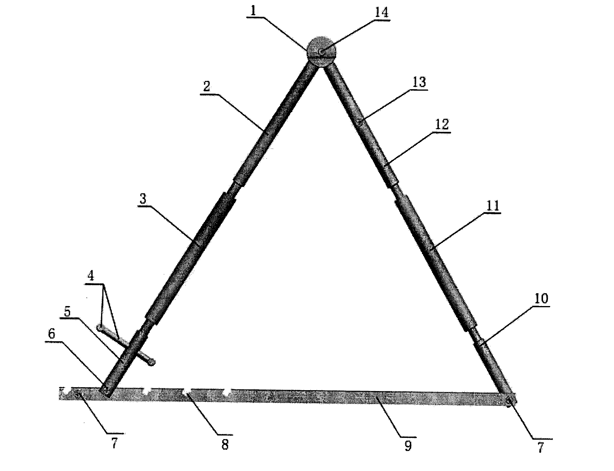
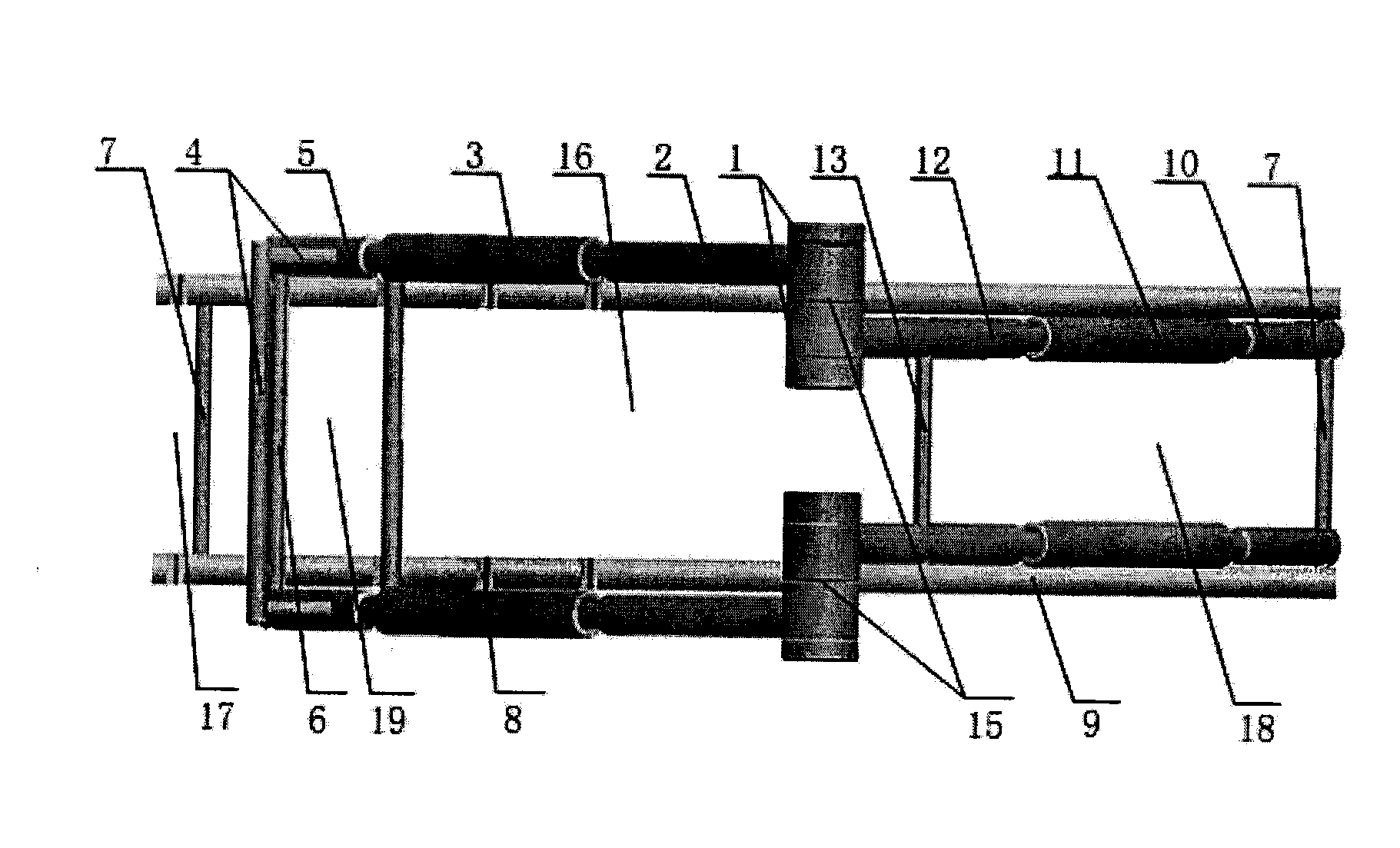
[0020] exist figure 1 , figure 2 , image 3 Among them, the tibial fracture closed reduction surgical frame includes a movable triangular surgical frame composed of a base frame 17, a front bracket 16, and a rear bracket 18. The underframe 17 is rectangular and is composed of a square tube 9 with a slot 8 and a fixed tube 7 for the underframe. The upper and lower sides of the front bracket 16 have the upper adjustment screw 2 and the lower adjustment screw 5 of the front bracket with reverse taps on the upper and lower sides, and the front bracket adjustment nuts 3 with corresponding taps at both ends are passed between the screw rods. connected. The upper and lower sides of the rear bracket 18 have the upper and lower adjustment screw rods 12 of the rear bracket with reverse taps and the lower adjustment screw rods 10 of the rear bracket, and the rear bracke...


PUM


Abstract

The invention discloses a closed reduction surgical frame for tibial fracture of a patient, and relates to a medical instrument for orthopedic surgery. The surgical frame mainly comprises a movable triangular surgical frame body. The triangular surgical frame body comprises a base frame, a front bracket and a rear bracket. A connection mode of the closed reduction surgical frame includes that front bracket upper adjusting screws on two sides of the front bracket and rear bracket upper adjusting screws on two sides of the rear bracket are correspondingly movably connected with one another by concentric shafts and rotary fixing nuts to form two independent support pillars, so that thigh fixing supports are jointly formed. The base frame is movably connected with the other end of the rear bracket by a base frame fixing rod. A fixing clamp shaft at the other end of the front bracket is movably connected with one of clamp grooves of the base frame. The closed reduction surgical frame has the advantages that a continuous traction effect can be realized during closed reduction for the tibial fracture of the patient, and the stability of reduction and the stability of a fracture end of the patient are maintained; compression on the nerves of the local popliteal blood vessels of the patient due to traction is prevented; flexion and extension angles of the knee joint of the patient can be adjusted at any time as needed during surgery, and the closed reduction surgical frame is simple in structure and easy to operate.

Description

technical field [0001] The invention relates to a medical instrument for orthopedic surgery, in particular to a tibial fracture closed reduction operation frame. Background technique [0002] At present, closed reduction of tibial fractures mainly includes manual reduction and reduction using special reduction tools. [0003] 1. Manual reset [0004] At present, manual reduction is still a commonly used method for closed reduction of tibial fractures. The reduction operation needs to be completed with the cooperation of multiple people, and the fracture end is reset by reverse traction on the distal and proximal ends of the fracture. Due to manual traction, reduction, and unstable maintenance, it is usually necessary to repeatedly reset, repeat fluoroscopy, and sometimes open reduction of the fracture end, which obviously affects the quality of tibial fracture surgery, and also increases the intake of X-rays for patients and medical staff quantity. [0005] 2. Special re...

Claims


Application Information

Patent Timeline
IPC IPC(8): A61B17/56
Inventor 董文伟史增元
Owner 董文伟
Learn More