
Pneumatic supply system

A supply system and pneumatic technology, applied in the direction of conveyor, transportation and packaging, conveying bulk materials, etc., can solve the problems affecting the stability of electric energy and generating safety hazards, etc., and achieve the effect of reasonable structure, safe transportation and convenient use

Inactive Publication Date: 2013-12-04
吴小冬
View PDF4 Cites 0 Cited by
  • Summary
  • Abstract
  • Description
  • Claims
  • Application Information

AI Technical Summary

Problems solved by technology

During the transmission of electric energy, high-voltage electricity is transmitted, which leads to potential safety hazards, and in the process of transmission, it is greatly affected by the external environment, which affects the stability of electric energy transmission

Method used


Image

  • Pneumatic supply system

Examples


Embodiment Construction

[0018] The present invention will be further described below in conjunction with specific embodiments and accompanying drawings.

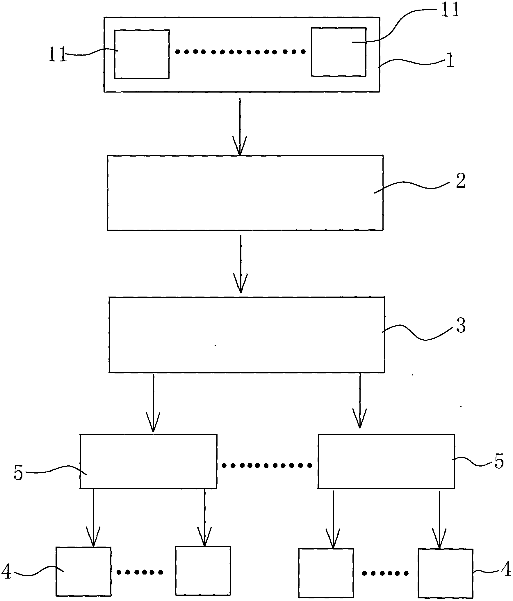
[0019] See figure 1 As shown, a pneumatic supply system includes: an air compression mechanism 1, the air compression mechanism 1 includes a plurality of disk compressors 11 to cooperate; a gas collection mechanism 2, the gas collection mechanism 2 is used to collect air compression The compressed gas generated by the mechanism 2 is connected to the air compression mechanism 1 through the pipe body; a gas delivery mechanism 3, which transports the compressed gas collected by the gas collection mechanism 2 to the pneumatic load 4 through the pipeline.

[0020] The disc compressor 11 includes a multi-stage compression device, wherein the outlet pipe in the upper stage compression device and the inlet pipe of the next stage are connected with an air storage tank, which can make the compression of the next stage The device provides air source and back...


PUM


Abstract

The invention discloses a pneumatic supply system. The pneumatic supply system comprises an air compression mechanism, an air collecting mechanism and an air conveying mechanism, wherein the air compression mechanism comprises a plurality of disc compressor in a matched mode; the air collecting mechanism is used for collecting compressed air produced by the air compression mechanism and is connected with the air compression mechanism through a pipe; the air conveying mechanism conveys the compressed air collected by the air collecting mechanism to a pneumatic load through a pipeline. According to the pneumatic supply system, the air compression mechanism is utilized to collect natural power and compresses the natural power into pneumatic energy, and the pneumatic energy is conveyed to the air collecting mechanism through the pipeline and then conveyed to the pneumatic load through the air conveying mechanism. The pneumatic supply system is reasonable in structure and safe in conveying, and provides the pollution-free pneumatic energy for the pneumatic load. According to the pneumatic supply system, sources of the pneumatic energy are extremely wide natural power (like wind), and the problem of energy shortage can be effectively resolved. In addition, the pneumatic supply system can effectively store and convey the pneumatic energy, and is easy and convenient to use.

Description

Technical field: [0001] The invention relates to the technical field of pneumatic energy transmission, in particular to a pneumatic supply system with a reasonable structure that can provide pollution-free energy. Background technique: [0002] At present, the energy used in daily life or industry is electric energy. Due to the progress of society, the energy sources (such as oil and coal) used for power generation such as oil are increasingly in short supply, which makes the supply of electric energy tense. [0003] The supply of electric energy is generated through a power station, and the electric energy is transformed through a transformer and then transmitted through a wire network. Before being transmitted to the load, the electric energy is transformed again through a transformer, and then the transformed electric energy is transmitted to the load. During the transmission of electric energy, high-voltage electricity is transmitted, which leads to potential safety haz...

Claims


Application Information

Patent Timeline
Patent Type & Authority Applications(China)
IPC IPC(8): B65G53/58B65G51/00
Inventor 吴小冬
Owner 吴小冬
Learn More