Swinging-arm-type flexible belt bundle winding machine

A technology of flexible belt and winding machine, which is applied in the direction of winding strips, thin material processing, transportation and packaging, etc., which can solve the problems of high drive motor power, high power consumption of equipment, and low space utilization, and reduce power consumption. consumption, precise control, and solve the effect of low equipment space utilization

Inactive Publication Date: 2013-12-04
严斯亮
View PDF8 Cites 6 Cited by
  • Summary
  • Abstract
  • Description
  • Claims
  • Application Information

AI Technical Summary

Problems solved by technology

[0005] In the current winding equipment, what needs to move back and forth in parallel is the rotating "inflatable shaft", including the "inflatable shaft", the driving motor, and the tape bundle wound on the "inflatable shaft". The quality

Method used


Image

  • Swinging-arm-type flexible belt bundle winding machine
  • Swinging-arm-type flexible belt bundle winding machine
  • Swinging-arm-type flexible belt bundle winding machine

Examples


Embodiment 1

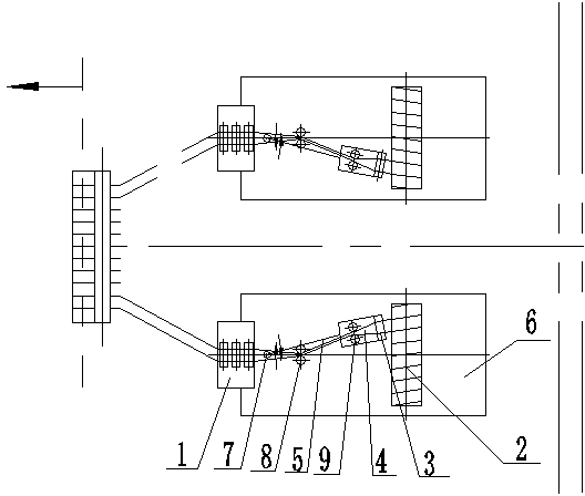
[0047] Use the fabric making machine or unwinding machine to first release the flexible tape material to a certain length, and the starting end of the released flexible tape material passes through the functional pulley block 1, the first tape section torsion pulley block 8, the second tape section torsion pulley block 9 and Tape export pulley 3, the starting end of the flexible strip passes through the strip export pulley 3 and then is wound on the inflatable shaft assembly 2 with adhesive tape, the strip exit pulley 3 and the second strip section torsion pulley block 9 are arranged on the export pulley mounting plate 4 Above, the lead-out pulley installation plate 4 is arranged on one end of the lead-out pulley swing arm 5, and the other end of the lead-out pulley swing arm 5 is connected with the swing arm shaft 7. The expansion shaft assembly 2 is arranged on the main body 6 of the winding machine. After starting the winding machine to complete the winding preparation work,...

Embodiment 2

[0051] Use the fabric making machine or unwinding machine to first release the flexible tape material to a certain length, and the starting end of the released flexible tape material passes through the functional pulley block 1, the first tape section torsion pulley block 8, the second tape section torsion pulley block 9 and Tape export pulley 3, the starting end of the flexible strip passes through the strip export pulley 3 and then is wound on the inflatable shaft assembly 2 with adhesive tape, the strip exit pulley 3 and the second strip section torsion pulley block 9 are arranged on the export pulley mounting plate 4 Above, the lead-out pulley installation plate 4 is arranged on one end of the lead-out pulley swing arm 5, and the other end of the lead-out pulley swing arm 5 is connected with the swing arm shaft 7. The expansion shaft assembly 2 is arranged on the main body 6 of the winding machine. After starting the winding machine to complete the winding preparation work,...

Embodiment 3

[0055] Use the fabric making machine or unwinding machine to first release the flexible tape material to a certain length, and the starting end of the released flexible tape material passes through the functional pulley block 1, the first tape section torsion pulley block 8, the second tape section torsion pulley block 9 and Tape export pulley 3, the starting end of the flexible strip passes through the strip export pulley 3 and then is wound on the inflatable shaft assembly 2 with adhesive tape, the strip exit pulley 3 and the second strip section torsion pulley block 9 are arranged on the export pulley mounting plate 4 Above, the lead-out pulley installation plate 4 is arranged on one end of the lead-out pulley swing arm 5, and the other end of the lead-out pulley swing arm 5 is connected with the swing arm shaft 7. The expansion shaft assembly 2 is arranged on the main body 6 of the winding machine. After starting the winding machine to complete the winding preparation work,...


PUM


Abstract

The invention relates to a swinging-arm-type flexible belt bundle winding machine, which comprises a functional pulley block, an inflatable shaft component and a belt guiding-out pulley. The belt guiding-out pulley is fixedly arranged on a guiding-out pulley mounting plate. The guiding-out pulley mounting plate is arranged at one end of a guiding-out pulley swinging arm. The other end of the guiding-out pulley swinging arm is connected with a swinging arm shaft which is arranged on a winding machine main body and can axially swing around the swinging arm shaft along the inflatable shaft component. A first belt section twisting pulley block and a second belt section twisting pulley block which are used for twisting flexible belts are additionally arranged between the functional pulley block and the belt guiding-out pulley. The first belt section twisting pulley block is fixedly arranged on the winding machine main body and is arranged opposite to the functional pulley block. The second belt section twisting pulley block is fixedly arranged on the guiding-out pulley mounting plate and is opposite to the belt guiding-out pulley. The swinging-arm-type flexible belt bundle winding machine has the advantages that the structure is simple, the stress is uniform and the belts can be effectively prevented from being wrinkled during winding.

Description

technical field [0001] The invention relates to a winding machine, in particular to a swing arm type flexible strip material bundle winding machine. Background technique [0002] At present, the existing flexible tape materials, such as the material for making the inner adsorption layer of "diapers", are composed of non-woven fabrics, fluff pulp and water-absorbent resin, etc. During the production and use process, the flexible tape materials need to be wound into Disc or bundle. Also, the tension in the flexible tape must be controlled during the winding process. [0003] If the tension is too small, it is easy to loosen after winding into a disc or bundle, which affects transportation, storage and use. However, if the tension is too large, the cross-sectional shape and size of the flexible strip will be affected, and the strip may even be broken. Therefore, in the winding process of the flexible tape, the tension of the flexible tape during the winding process should be...

Claims


Application Information

Patent Timeline
IPC IPC(8): B65H20/02B65H23/34B65H20/30B65H23/16
Inventor 胡嘉林钱立王一飞胡科
Owner 严斯亮
Why Eureka
Try Eureka