Pipe joint

A technology for pipe joints and root canals, applied in the field of pipe joints, can solve problems such as difficult fastening operations, increased construction costs, and high flange prices, and achieves the effects of easy construction, improved constructability, and low production costs

Active Publication Date: 2013-12-04
NAGAOKA INT
View PDF12 Cites 3 Cited by
  • Summary
  • Abstract
  • Description
  • Claims
  • Application Information

AI Technical Summary

Problems solved by technology

This flange is machined to grind and smooth the joint surface, so the airtightness when connecting the pipes is good, but the price of the flange is high, which increases the construction cost. In the case of connecting the pipes horizontally , it is extremely difficult to insert the bolts into the bolt holes on the lower side of the flange and fasten them, and there is a difficulty in the work.

Method used


Image

  • Pipe joint
  • Pipe joint
  • Pipe joint

Examples


Embodiment Construction

[0042] Preferred embodiments of the present invention will be described below with reference to the drawings.

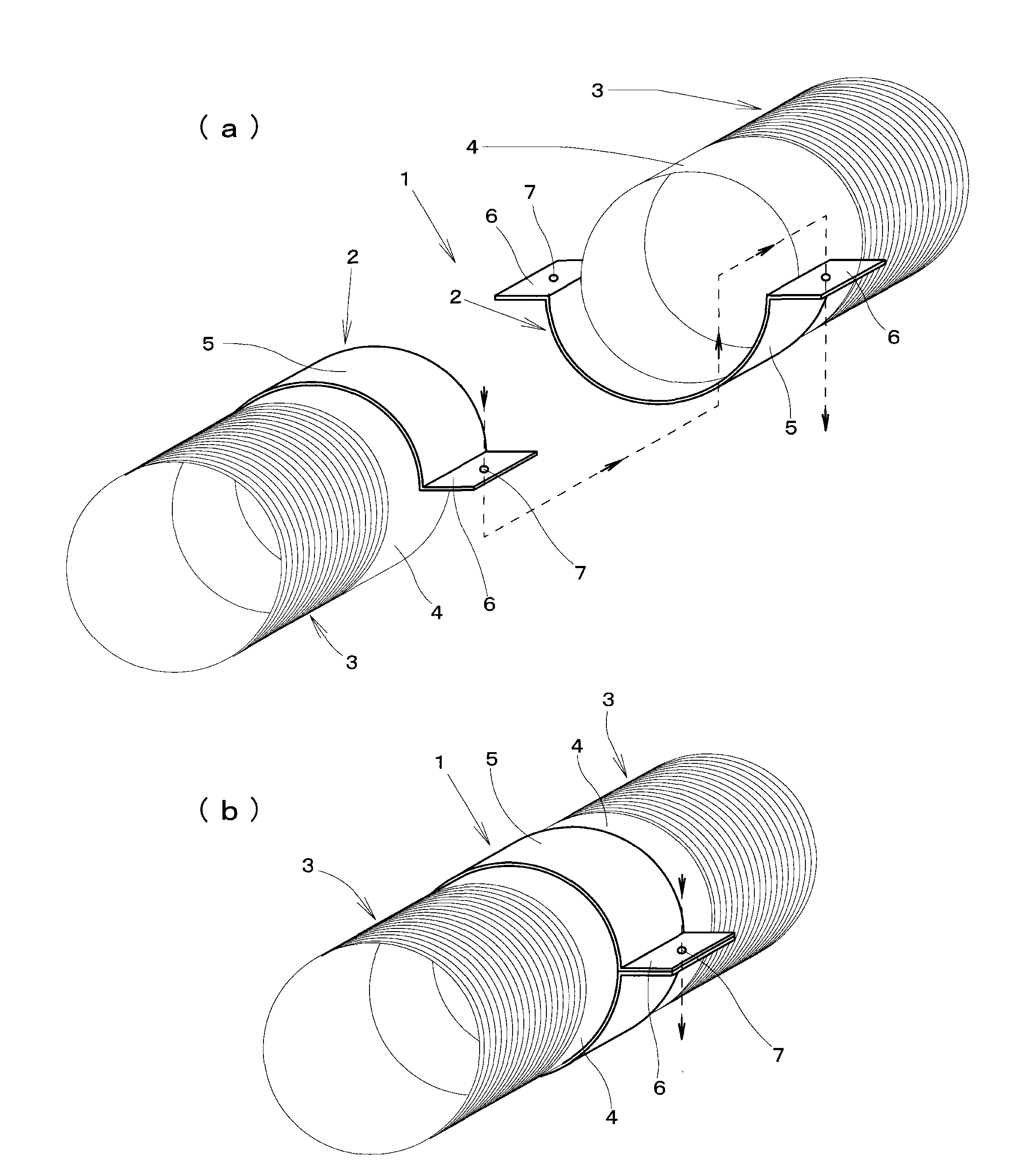
[0043] figure 1 It is a perspective view showing a basic embodiment of the pipe joint of the present invention, figure 1 (a) is a figure which shows the state before connecting a joint, figure 1 (b) is a figure which shows the state after connecting a joint.

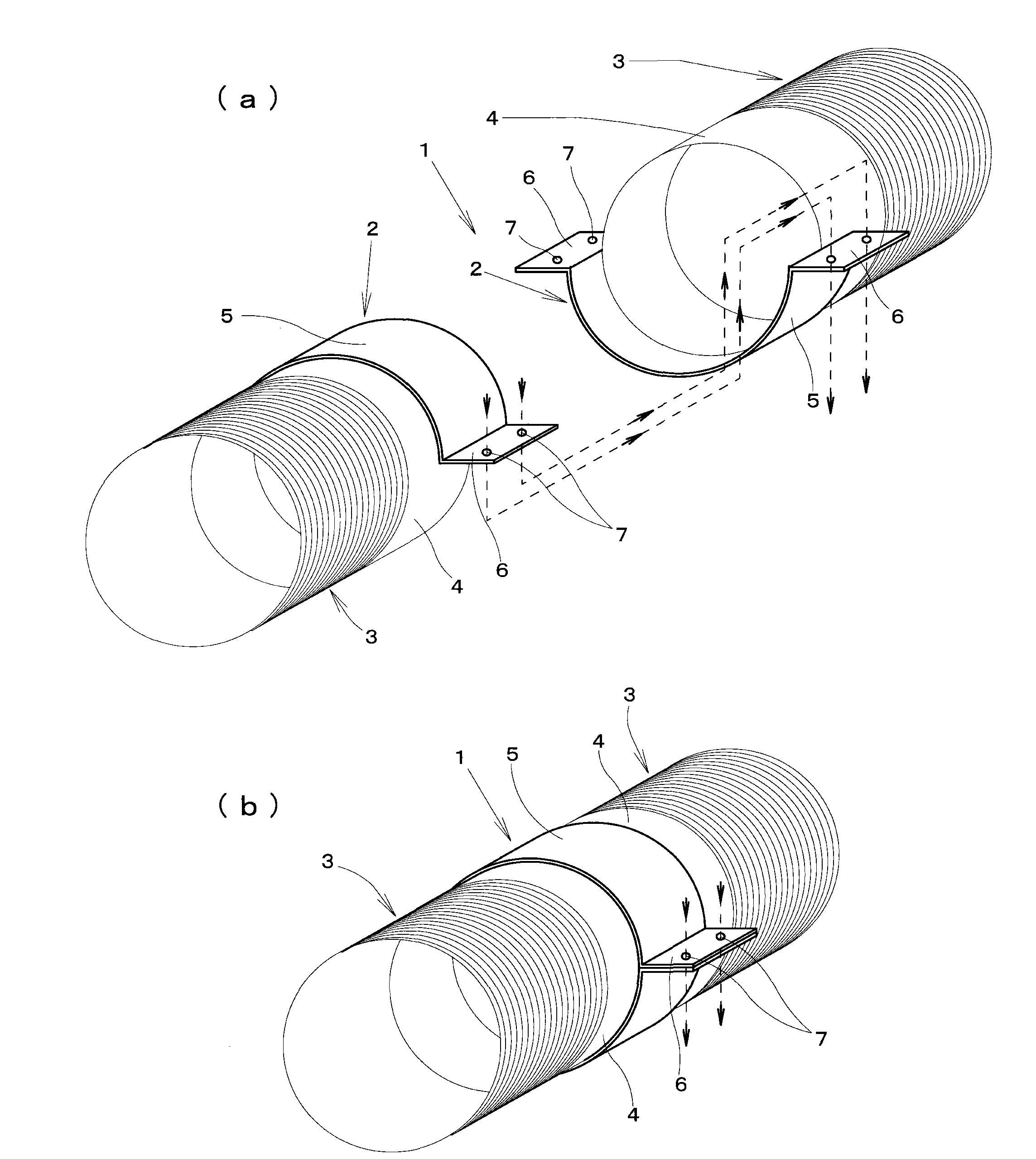
[0044] This embodiment is an embodiment corresponding to the second configuration in the above-mentioned "Summary of the Invention" column, and it is a preferable implementation in the case of using for connecting a plurality of pipes in a horizontal state at a construction site such as a sewer ditch. Way.

[0045] This embodiment and the embodiments described below are described as pipe joints for connecting curtain pipes, but the pipes to be connected are not limited to curtain pipes, and may be ordinary cylindrical steel pipes or resin pipes. . In addition, although the pipe joints used in this embodime...


PUM


Abstract

The invention provides a novel pipe joint, which has necessary and sufficient functions as a pipe joint such as for a water supply steel pipe, and simultaneously improves an application property. The pipe joint (1) provided by the invention comprises: straps (5, 5) which are welded on a part of the external circumferential surface of each connection end (4, 4) of two connected pipes (3, 3) and are used for fixing flanges; and a pair of plate-shaped flanges (6, 6) which extend along a direction parallel to a pipe shaft, and are formed at external sides of the straps (5, 5) for fixing the flanges at two positions opposite to the radial directions of the pipes, wherein connection holes (7, 7) for inserting fasteners are arranged on each flange, and the straps (5, 5) for fixing the flanges enable the pipe shafts to only extrude a specified distance to the external parts away from the end edges.

Description

technical field [0001] The present invention relates to a pipe joint, and in particular, to a pipe joint suitable as a joint for steel pipes for water supply, such as steel pipes used for wells for taking in groundwater, and steel pipes for catchment drains. Background technique [0002] As a method of connecting a plurality of pipes used as steel pipes for water supply, etc., the simplest method is a method of welding adjacent end portions of two pipes to be connected. However, with the welding method, although it is possible to connect pipes straightly when welding in a factory, it is difficult to connect straightly at a construction site such as a catchment ditch, and standard deviation tends to occur, resulting in the difficulty of poor processing accuracy. . [0003] In addition, there is another method, which is to provide external threads on one end of the two pipes to be connected, provide internal threads on the other end, and screw one end to the other end. On th...

Claims


Application Information

Patent Timeline
Patent Type & Authority Applications(China)
IPC IPC(8): E03B3/16E03B3/40F16L21/06
Inventor 三村等林野田中诚一郎
Owner NAGAOKA INT
Why Eureka
Try Eureka