Supercharge Your Innovation With Domain-Expert AI Agents!

Turbine compressor

A technology of a turbo compressor and a cylinder, applied in the field of gas compressors, can solve the problems of high cost, small impeller width, and inability to manufacture

Active Publication Date: 2013-12-04
王雁南
View PDF5 Cites 0 Cited by
  • Summary
  • Abstract
  • Description
  • Claims
  • Application Information

AI Technical Summary

Problems solved by technology

Since the cylinder is fixed, there is relative motion between the impeller and the cylinder, and the rotating speed of the rotor is very high. In order to prevent the high-pressure gas from returning between the stages, a labyrinth seal must be used, which requires high manufacturing precision and assembly precision, resulting in Expensive, especially when manufacturing small flow compressors, as the width of the impeller is very small, making it almost impossible to manufacture

Method used


Image

  • Turbine compressor
  • Turbine compressor
  • Turbine compressor

Examples


Embodiment Construction

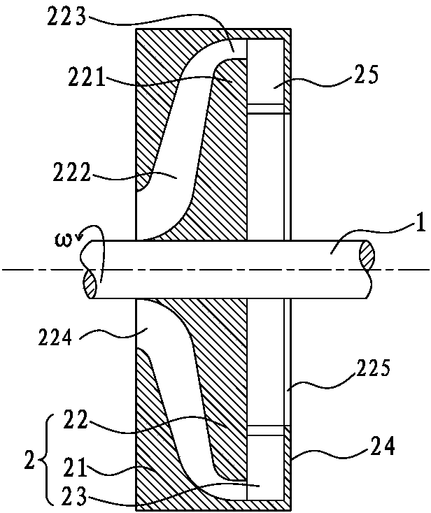
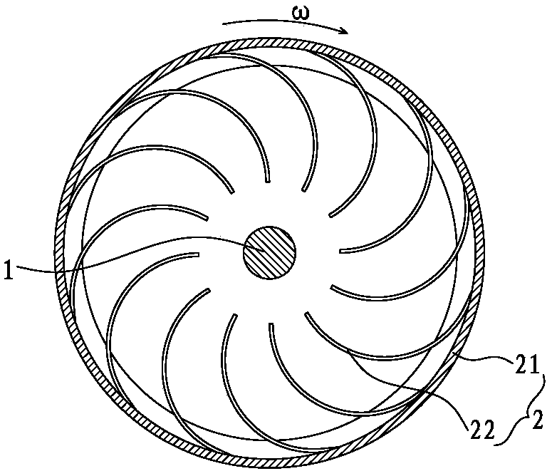
[0022] like figure 1 , figure 2 Shown, the present invention: the basic structure of the primary rotor of a kind of turbocompressor, it comprises rotating shaft 1, rotor 2.

[0023] The rotor 2 is composed of a cylinder 21 , an impeller 22 , several forward arc-shaped blades 23 uniformly distributed along the circumference, and an end cover 24 . The cylinder 21 is installed outside the impeller 22, and the cylinder 21 and the impeller 22 are integrated and fixedly installed on the rotating shaft 1. The rotating shaft 1 is used to install and support all other components and drive them to rotate together at high speed. Described end cover 24 is installed on the gas outlet end of cylinder 21, and cylinder 21, end cover 24 and other elements form the air chamber of external closure together, and gas can only enter and exit through air inlet 224, air outlet 225. A plurality of blades 221 on the impeller 22 and the cylinder 21 together form a plurality of flow passages, each flo...


PUM


Abstract

The invention discloses a turbine compressor. The turbine compressor comprises a rotating shaft and a first level rotor or a rotor above the first level. The rotor is mainly formed by an air cylinder, an impeller, forward arc-shaped blades and an end cover; the air cylinder and the impeller which are integrated into a whole are fixedly arranged on the rotating shaft; the forward arc-shaped blades are arranged at the rear end of the impeller. According to the turbine compressor, the air cylinder and the centrifugal impeller which are coaxial rotate simultaneously, relative motion is not generated between the air cylinder and the impeller, and meanwhile relative motion is not generated between different levels, so that clearance fit between the dynamic seal and the high accuracy is not needed to be designed, machining, manufacturing and assembling are simple, and the sealing performance is good.

Description

technical field [0001] The invention relates to a gas compressor, in particular to a turbo compressor in which a cylinder and an impeller rotate coaxially. Background technique [0002] The turbo compressor makes the gas move at high speed through the impeller, and then converts the kinetic energy of the gas movement into pressure energy. In order to obtain sufficient pressure, a multi-stage impeller is required. Whether it is a centrifugal or axial flow turbine, it needs to work under the interaction of the rotating impeller (rotor) and the stator (fixed blades or cylinder). For example, the structure of a centrifugal turbocompressor is composed of an impeller (also called a rotor) and a cylinder (also called a stator). When the impeller rotates, the air flow flows to the outer edge of the impeller at high speed. During this process, the gas obtains kinetic energy. The gas enters the inner edge of the next-stage impeller through the bend in the cylinder, and the kinetic e...

Claims


Application Information

Patent Timeline
IPC IPC(8): F04D23/00
Inventor 王雁南
Owner 王雁南
Features
  • R&D
  • Intellectual Property
  • Life Sciences
  • Materials
  • Tech Scout
  • Unparalleled Data Quality
  • Higher Quality Content
  • 60% Fewer Hallucinations
Learn More