Heat dissipation device and lighting device with the heat dissipation device

A technology for a heat sink and a lighting device, which is applied to lighting devices, cooling/heating devices for lighting devices, lighting and heating equipment, etc. problems, to achieve the effect of reducing production costs and reducing manufacturing difficulty

Active Publication Date: 2018-02-13
LEDVANCE GMBH
View PDF4 Cites 0 Cited by
  • Summary
  • Abstract
  • Description
  • Claims
  • Application Information

AI Technical Summary

Problems solved by technology

However, there is an obvious disadvantage of this type of heat sink, that is, its relatively large volume and reduced air convection between the fins
For this reason, it is proposed in the prior art to open holes on the heat sink or design heat sinks with various special shapes, but this reduces the contact area between the heat sink and the convective air to a certain extent, and reduces the heat dissipation of the heat sink. performance
At the same time, the structure of the heat sink of the above type is complicated, and it is not easy to process and manufacture, which increases the manufacturing complexity and cost of the heat sink
[0004] In addition, the simple sheet-shaped heat sink is simpler and easier to manufacture, and the cost is low, but it has a fatal defect, that is, when the air flows over the surface of the sheet-shaped heat sink, a kind of airflow is formed on the surface of the heat sink. Thermal boundary layer or temperature boundary layer, which significantly increases the thermal resistance of the heat sink and reduces the heat dissipation performance of the heat sink

Method used


Image

  • Heat dissipation device and lighting device with the heat dissipation device
  • Heat dissipation device and lighting device with the heat dissipation device
  • Heat dissipation device and lighting device with the heat dissipation device

Examples


Embodiment Construction

[0023] In the following detailed description, reference is made to the accompanying drawings which form a part hereof, and in which are shown by way of illustrations specific embodiments in which the invention may be practiced. With respect to the figures, directional terms such as "top", "bottom", "front", "rear", "longitudinal", "circumferential", etc. are used with reference to the orientation of the figures being described. Since components of embodiments of the present invention may be placed in many different orientations, the terminology of orientation is used for illustration only and not in any limiting sense. It is to be understood that other embodiments may be utilized and structural or logical changes may be made without departing from the scope of the present invention. Therefore, the following detailed description should not be taken in a limiting sense, and the invention is defined by the appended claims.

[0024] figure 1 A schematic diagram of a first embodi...


PUM


Abstract

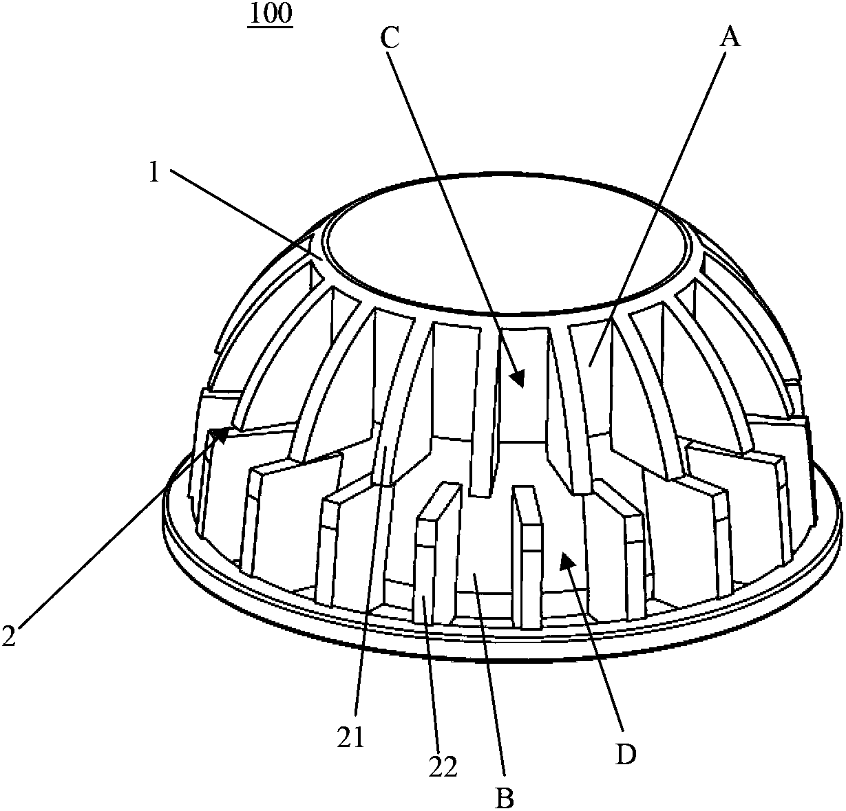
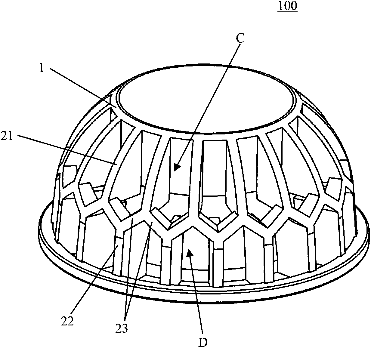
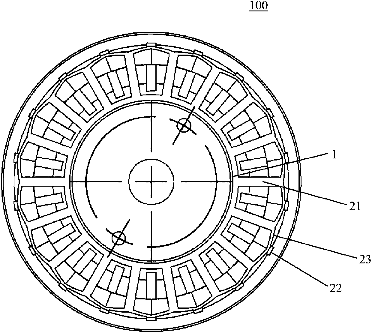
Heat dissipation device (100) for an illumination apparatus, comprising a base (1) comprising a first section (A) and a second section (B) provided in a longitudinal direction, and a heat dissipation structure (2), wherein, the heat dissipation structure (2) comprises a plurality of first fins (21) distributed on a circumferential surface of the first section (A) and a plurality of second fins (22) distributed on a circumferential surface of the second section (B), and a circumferential angular position of the first fin (21) is different from a circumferential angular position of the second fin (22). In addition, the present invention also relates to an illumination apparatus comprising the heat dissipation device (100).

Description

technical field [0001] The invention relates to a heat dissipation device for an illuminating device. In addition, the present invention also relates to an illuminating device with the heat dissipation device of the above type. Background technique [0002] LED replacement lamps such as types like MR16, PAR16, PAR20, Classic A and Classic B are increasingly replacing traditional lighting fixtures such as incandescent and fluorescent lamps. This is because replacement lamps of this type are more energy efficient, smaller in size and have a longer life. With the development of technology, the LED package itself can achieve higher efficiency, for example, it can obtain 140lm / W cool white light and 90lm / W warm white light, and its life span can reach 50,000 hours. But when LEDs are integrated into replacement lamps along with LED drivers, thermal management devices, and optics, the efficiency and lifetime of the replacement lamps are highly dependent on how the drivers, heat s...

Claims


Application Information

Patent Timeline
Patent Type & Authority Patents(China)
IPC IPC(8): F21V29/77F21Y115/10
CPCF21V29/507F21V29/75F21V29/773F21V29/83F21V29/87F21V29/89
Inventor 何国安王明涛王万濮
Owner LEDVANCE GMBH
Why Eureka
Try Eureka