Optical cable junction box
A technology of optical cable joint box and box seat, which is applied in the direction of fiber mechanical structure, etc., can solve the problems of inconvenient sealing operation of optical cable, poor design of sealing structure at the inlet and outlet ends, etc., and achieve the effect of quick operation and maintenance
- Summary
- Abstract
- Description
- Claims
- Application Information
AI Technical Summary
Problems solved by technology
Method used
Image
Examples
Embodiment Construction
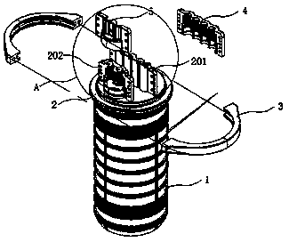
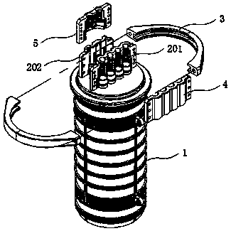
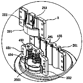
[0028] The following will be combined with Figure 1-6 The present invention is described in detail:
[0029] Such as figure 1 , 2 As shown, an optical cable splice box includes a box body 1, a box seat 2, wire inlet and outlet devices 201, 202, and cover plates 4, 5. The box body 1 is fastened to the box seat 2, and the fastening place is provided hoop 3 and sealing ring, the box seat 2 is provided with an optical fiber storage tray, the box seat 2 is provided with an incoming and outgoing line through hole, and the outer side of the box seat 2 is provided with a position corresponding to the described incoming and outgoing line through hole The wire inlet and outlet devices 201, 202 integrated with the box base 2, the cover plates 4, 5 are sealed and fastened with the wire inlet and outlet devices 201, 202 through a plurality of screws or rivets, for example, 3-10 M4- M12 screws are sealed and fastened, and the cover plates 4, 5 are fastened with the wire inlet and outlet...
PUM
 Abstract
Description
Claims
Application Information
 - R&D
- Intellectual Property
- Life Sciences
- Materials
- Tech Scout
- Unparalleled Data Quality
- Higher Quality Content
- 60% Fewer Hallucinations
Browse by: Latest US Patents, China's latest patents, Technical Efficacy Thesaurus, Application Domain, Technology Topic, Popular Technical Reports.
© 2025 PatSnap. All rights reserved.Legal|Privacy policy|Modern Slavery Act Transparency Statement|Sitemap|About US| Contact US: help@patsnap.com


