DC-DC Converter

A DC-DC, converter technology, applied in the field of DC-DC converters, can solve the problems of error amplification, large surge voltage, intense noise, etc.

Inactive Publication Date: 2013-12-04
KK TOSHIBA
View PDF1 Cites 3 Cited by
  • Summary
  • Abstract
  • Description
  • Claims
  • Application Information

AI Technical Summary

Problems solved by technology

[0008] Since the short-circuit current generated by the recovery current has a sharp needle-shaped waveform, it brings a large surge voltage and causes intense noise. In v

Method used


Image

  • DC-DC Converter
  • DC-DC Converter
  • DC-DC Converter

Examples


Example Embodiment

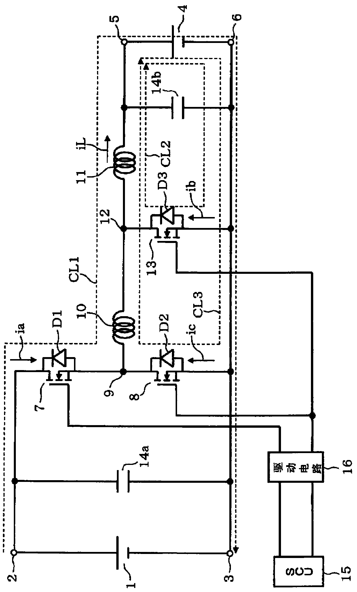
[0015] In showing the first embodiment figure 1 Among them, the DC-DC converter has a DC voltage positive input terminal 2 connected to a DC power supply 1 and a DC voltage negative input terminal 3 on its input side, and a DC voltage positive output terminal 5 connected to a load 4 on its output side. And DC voltage negative side output terminal 6. Here, the positive side and the negative side only mean relatively indicating the level of potential. The DC power supply 1 refers to a DC power source including a battery, an AC-DC conversion rectifier circuit, and the like. The load 4 includes a resistive load, an inductive load such as a motor, a charged battery, or a load similar to them.

[0016] The first main switching element 7 and the auxiliary switching element 8 are connected in series between the DC voltage positive side input terminal 2 and the DC voltage negative side input terminal 3 so that the former is on the positive side and the latter is on the negative side. Th...


PUM


Abstract

A DC-DC converter includes a main reactor interposed in a main energization path extending from a DC voltage input terminal to a DC voltage output terminal, a first main switching element interposed into the main energization path so as to be on-off controlled so that current flowing across the main reactor is intermitted, a second main switching element forming a discharge loop discharging electrical energy stored in the main reactor to the DC voltage output terminal side, an auxiliary reactor interposed between the first main switching element and the main reactor in the main energization path, an auxiliary switching element discharging electrical energy via the main reactor to the DC voltage output terminal side, the electrical energy being stored in the auxiliary and main reactors, and diodes connected in reverse parallel with the first and second main switching elements and the auxiliary switching elements respectively.

Description

technical field [0001] Embodiments of the present invention relate to DC-DC converters that convert DC voltages into other DC voltages having different values. Background technique [0002] The DC-DC converter has the function of stepping down or boosting the DC voltage output from the DC power supply and converting it into other DC voltages with different values. It is a DC with feedback and PWM (Pulse Width Modulation: Pulse Width Modulation) control added. The function of stabilizing the power supply usually consists of two switching elements, a reactor, and a freewheeling diode to form a DC chopper circuit. Basically, the first and second main switching elements are connected in series between the positive and negative terminals of the DC power supply, and the reactor is connected in parallel to the second main switching element on the negative side via a load. Each switching element is connected in parallel to a snubber diode or a free-wheeling diode. The first and se...

Claims


Application Information

Patent Timeline
IPC IPC(8): H02M3/155H02M1/32
CPCG05F3/24H02M1/38H02M1/44H02M3/158H02M1/0051Y02B70/10
Inventor 筱原尚人永井一信
Owner KK TOSHIBA
Why Eureka
Try Eureka